Responsibilities part three - joint resistance in hollow section trusses

Welcome to the most trivial hill upon which I will gladly die. Also, when I say trivial really I’m trying to manipulate you a little with self-deprecation. It’s not trivial; this issue is a constant pain in my proverbial butt-weld. This is in fact, to me, The Big One.

Much like an item mentioned previously, the web-to-flange welds in plate girders, it’s hard to see how the responsibility of this particular design element ever moved from consultant to fabricator. In fact, both situations are directly analogous. I hope to persuade all who read this missive to join me on my hill, trivial or otherwise.

Ok - so what’s got your knickers in a twist? 

I’m going to lay this out one step a time as if I’m Hercule Poirot himself explaining to the reader exactly how events must have unfolded so as to arrive at the unavoidable conclusion that he is (or in this case I am) correct. Let’s begin at precisely the wrong end: the assumed and false denouement, the thing that has, in fact, got my knickers in a twist.

The claim: the steel fabricator is expected to always be able to connect up a truss designed by a third party

Oof. That hurts even just to look at.

When trusses are designed by consultants, they are presented to the fabricator as a finished item that simply needs to be connected up. If you’re lucky you will receive connection loads marked on the members of any truss, but usually you are given a table with just the maximum loadings for any given section size. You are then expected to “just connect it all up” whilst “just making it all work”. 

Starting at the start, I will show you why that is almost always impossible, and why we fabricators find ourselves entangled in a design process which should have been completed long before we are brought onto a project.

First we must ask ourselves: What exactly is a truss? 

A truss, for the purposes of today’s article, can be thought of as a single, large structural element made up of smaller elements. The simplest form of truss is the pin truss, and to keep this article at a sensible word count, this type alone will serve perfectly as our example for the day. 

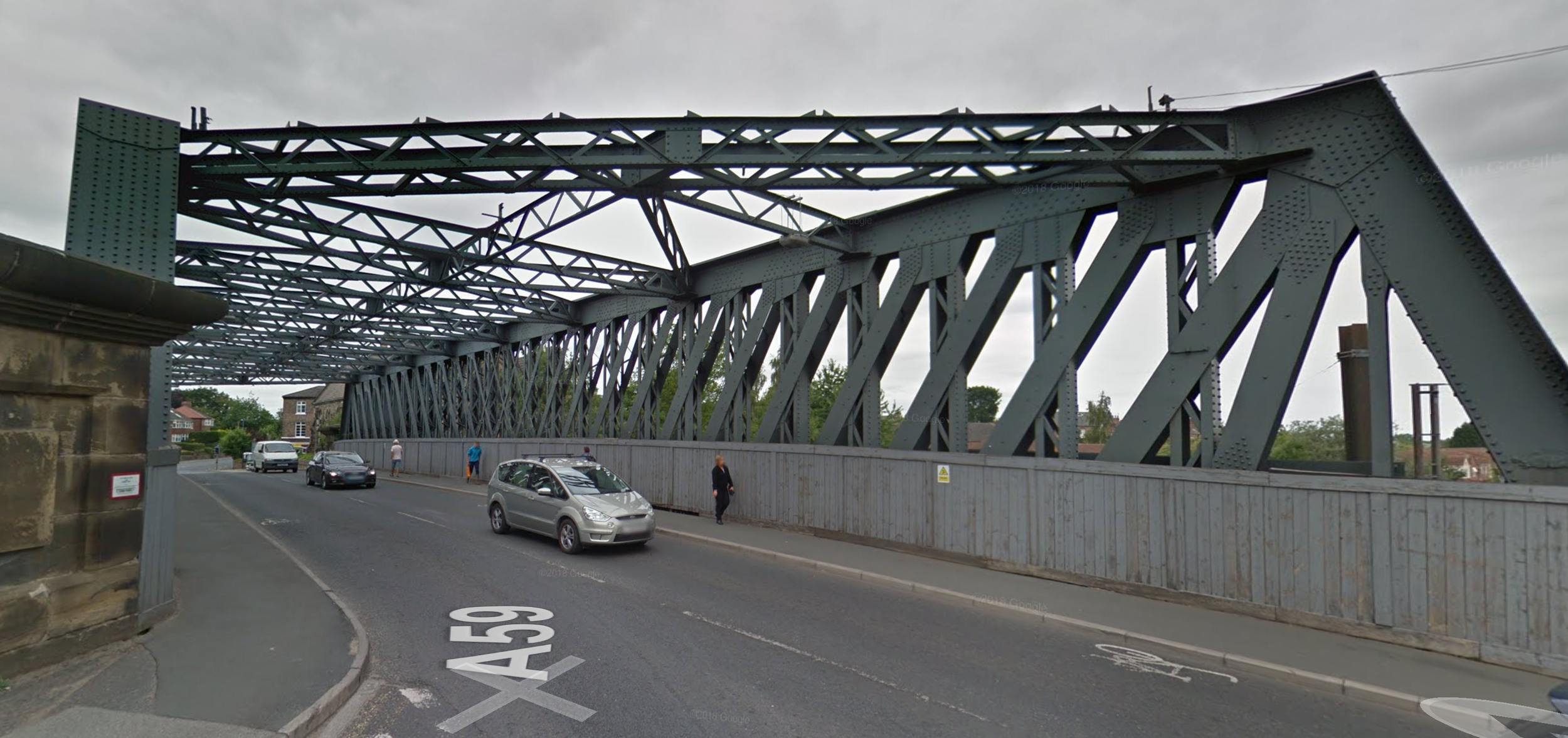
You’ve definitely seen them in the wild. They look like this:

IMG_0733.JPG

Or this: 

IMG_0734.JPG

Or even this: 

IMG_0735.PNG

But engineers prefer to think of them as looking like this: 

IMG_0736.PNG

You see the thing about pin trusses is that they can be shown to follow very simple rules if we pretend they are made of infinitely thin lines, the lines all meet at common points, and every joint occurs at a purely pinned connection (hence the name).

To allow us to talk about the various parts of the truss we have specific names for the main elements. We usually call the horizontal parts booms or chords, and we usually refer to the other parts as the internals, though sometimes we call them the diagonals and verticals depending on their orientation. We call the intersection points nodes.

In pin trusses, as long certain rules are followed the lines themselves never bend; they only experience either compression or tension. What all of those rules are isn’t important for this discussion, but the one about members all meeting at a common pinned node is.

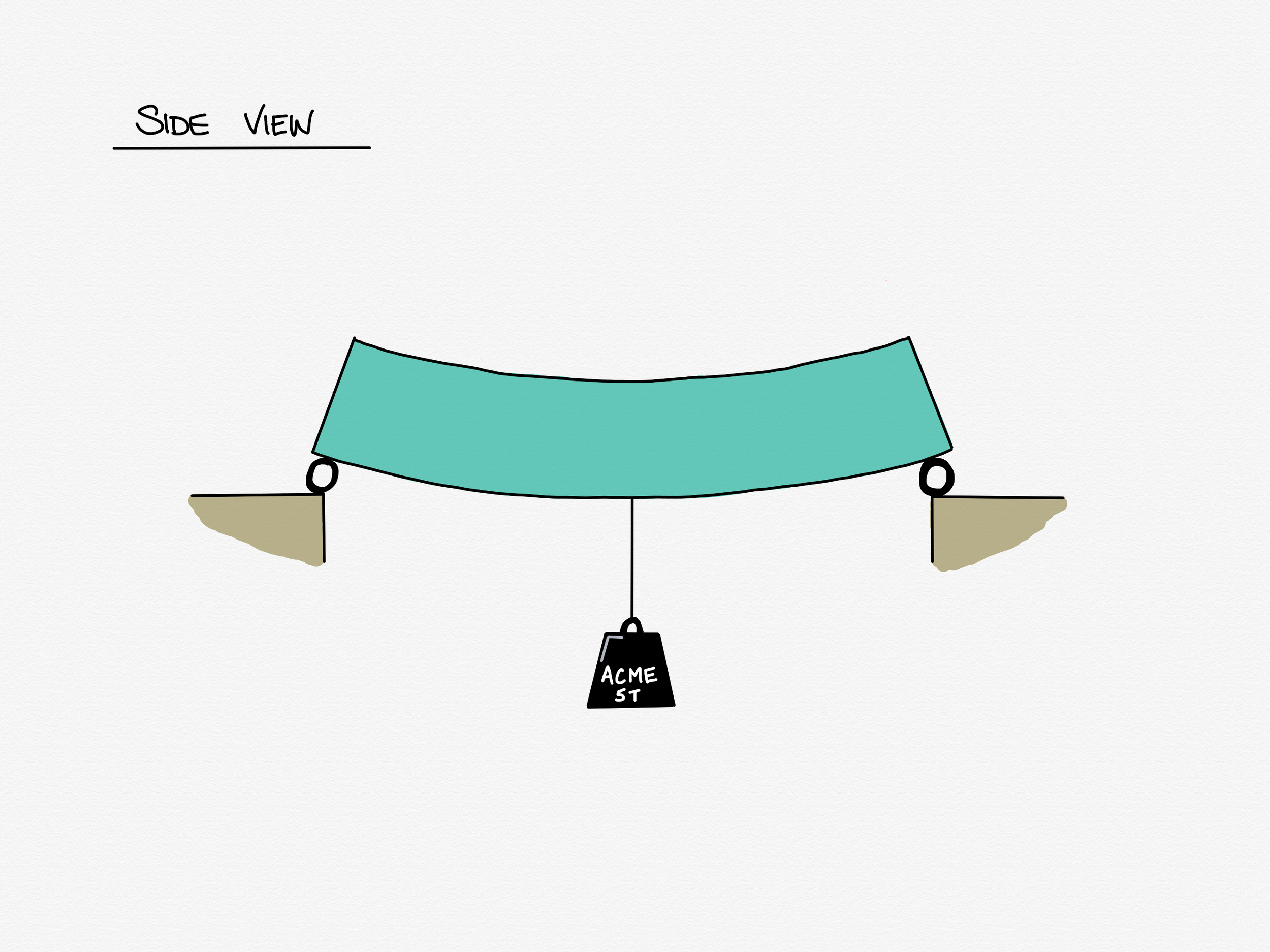
Excellent. We have now described an idealised model of a pin truss made up of line elements connected at pin joints. We know that the truss itself acts like one big element, and in our case that element will be analogous to a beam. And, because I am masquerading as Hercule Poirot I invite you now to imagine me fastidiously straightening the various items on my desk before taking a deep breath and barrelling on.

I’m with you so far, but what does this have to do with connections?

What this has to do with connections is the tension between the ideal and the real.

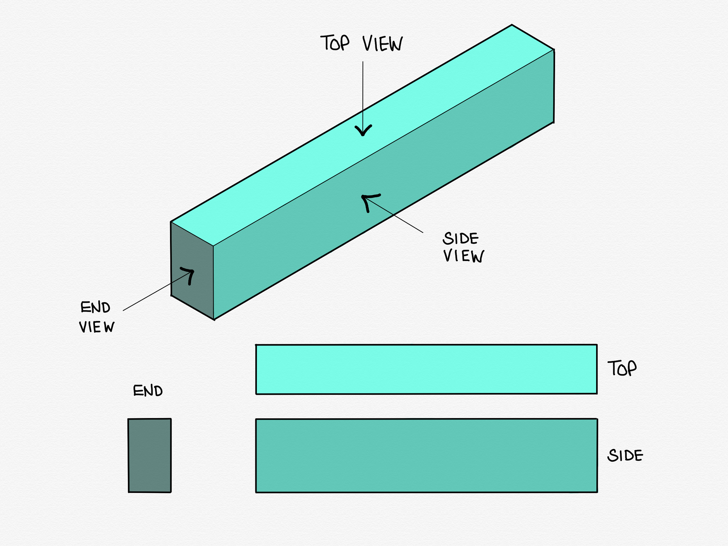
When we draw those infinitely thin lines representing the parts of the truss, we draw them down the centreline of the real lump of metal it represents, like this:

IMG_0737.PNG

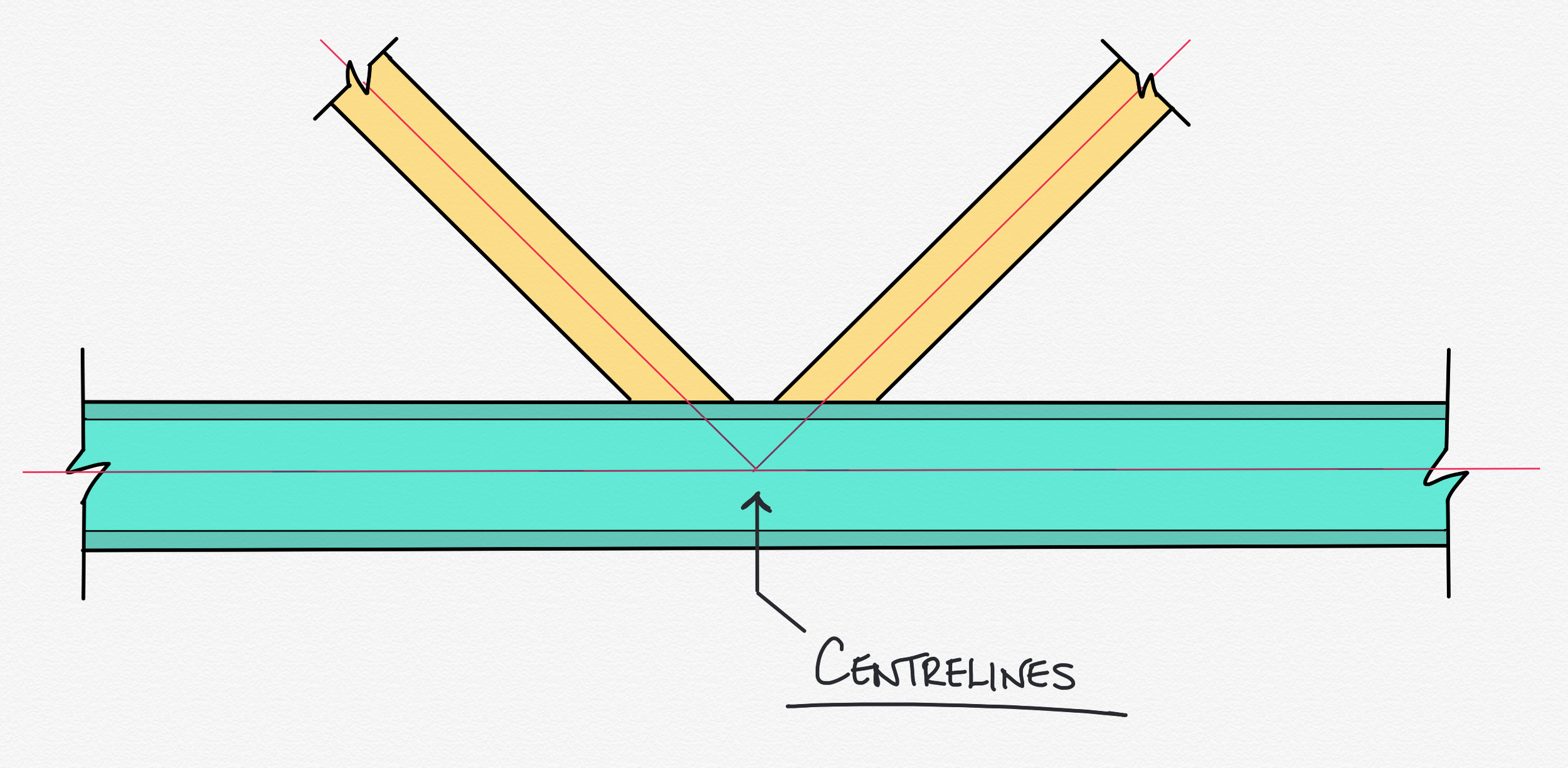
Which is fine - we do this all the time. What matters is that it is easy to forget at the design stage that those lines represent something physical; something with shape, volume, and mass.

As per classic Poirot, I’ve sneakily held something back. Something crucial, something that when you look back on it seems so obvious, but often when you’ve had your head in the detail you might forget the bigger picture.

There are rules about how those physical chunks of metal can and cannot be connected. Some of them are simple, common sense rules, and some of them a little more complex, but they are there, they are required, and they are entirely unavoidable. Let’s get on and take a look: the simplest rules to understand from a common sense perspective are the geometric validity rules, and those about member classification.

Rules part one: Geometric validity rules. Specifically, eccentricity 

Depending on the size and angle of the diagonals and verticals, rules about maximum or minimum gaps or overlaps between members might end up broken, and things need to be shuffled about slightly to accommodate. The way that you move them to make them valid is usually to move the intersection points of the diagonals away from the nodes. This causes what we call eccentricity - see below:

IMG_0738.PNG

Looks ok? Nothing to worry about? Let’s put some metal on those centreline bones... 

IMG_0739.PNG

Ah. Whilst this might look ok, it is in fact... not. Not only does it fall outside the geometric limits, it is impossible to fabricate, as it requires laying weld on top of weld. We have to alter the geometry to make this valid. 

IMG_0740.PNG

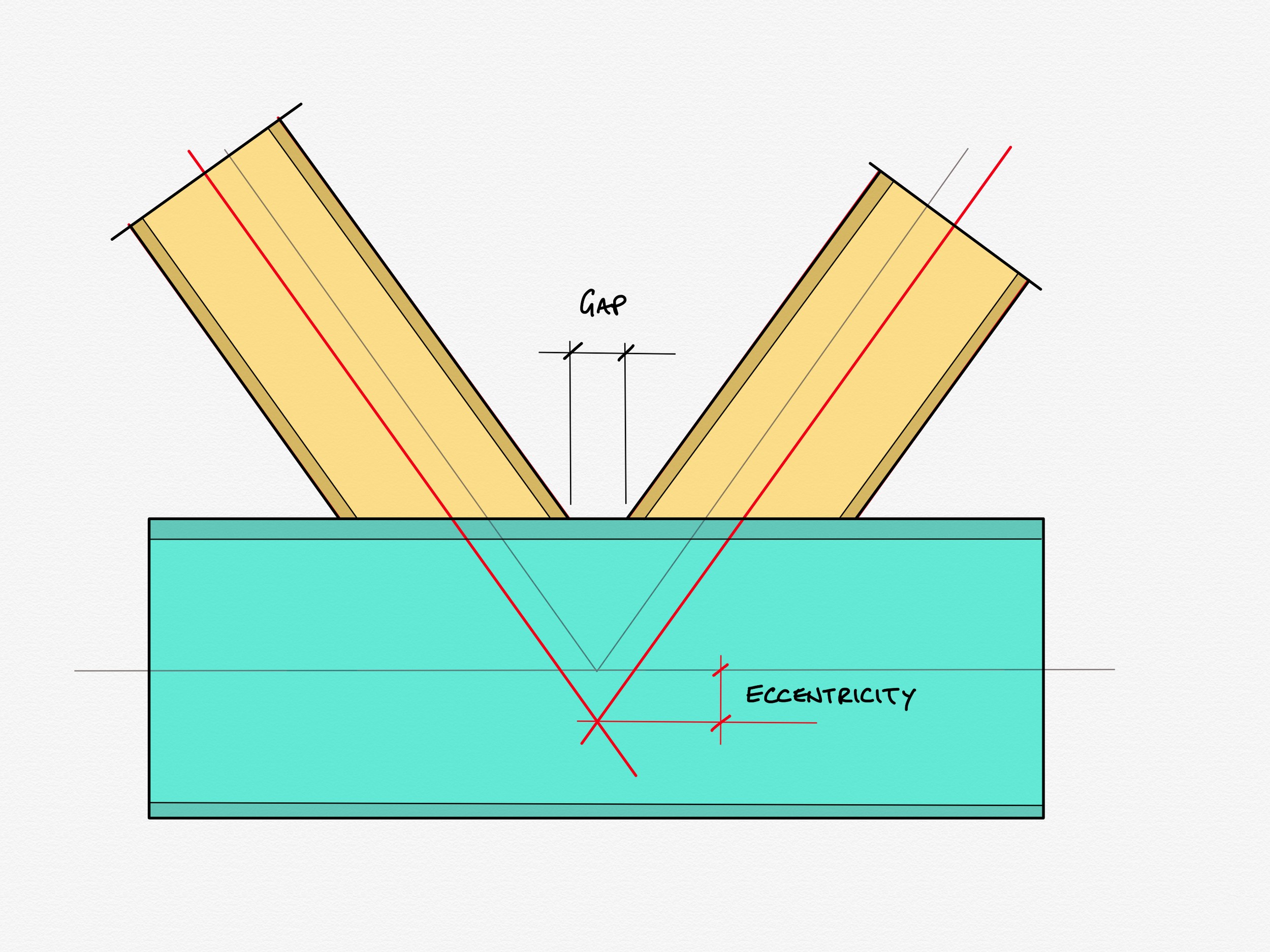
One solution is to pull the node apart like so, creating a decent gap between the noses of the diagonals. Alternatively the members could be overlapped even more, however that is more expensive to fabricate, as it means double cutting one of the diagonals.

Hopefully this starts to ring alarm bells.

If we “un-node” a joint sufficiently, we start to creep away from our idealised model to something a bit more… flimsy.

There a suite of formulae that comprise the CIDECT guide to truss connections which govern exactly how eccentric a connection is allowed to become before it is necessary to take account of the secondary bending induced in the booms, and the overall stiffness of the joints, and the overall stiffness of the whole truss. You can see an extract of the CIDECT guide below showing the validity limits we are forced to work to:

IMG_0741.PNG
IMG_0742.PNG

Here we see demonstrated a common problem: It is extremely rare that a truss is sent to our office that needs no alteration. I can think of only a couple of instances in the last decade or so where I have not had to send alterations like this back for review.

Rules part two: Member classification  

As usual, I’m going to overlook many details and caveats in this next paragraph to avoid layer up on layer of footnote, and to get to the conclusion before I lose you all. Let’s just get going and crash on through regardless.

Member classification is, on a surface level, even easier to understand than noding. Members are broken into 4 classes based on their chunkiness, with Class 1 being the most chunksome, and Class 4 being the most flappy. The rule is that members in hollow section trusses must be either Class 1 or Class 2. Lower class members are deemed to be too flimsy to play nicely. 

This rule is not as often broken as the geometric ones, but it does happen. 

The denouement  

Mes enfants. 

Sorry, couldn’t resist.

Sorry, couldn’t resist.

We arrive here at the denouement. The chapter where Papa Poirot assembles all the suspects, and leads you through the hidden story - the narrative that happened while you weren’t looking. 

We start with the simple question: “who is repsonsible for what?”.

The truss designer is responsible for the overall meta-member itself. If someone other than they were to sabotage the strength of that finished truss, for example to cut pieces out, or to substitute weaker material the designer would be upset, non? Of course they would. They would act to prevent such a thing occurring.

Therefore: 

If the truss designer were to send his truss to be connected up by a third party, and that same third party were forced to make changes that had a detrimental effect on the performance of the final member, the original designer would be equally as troubled, n’est-ce pas?

As it transpires: non. 

Truss designers regularly send their designs out to be fabricated, unaware that those designs are unfinished. They physically cannot be made to the desired specification, and must be altered, and often to some degree of detriment to the truss as whole. Is it right that some third party, completely disconnected from the design requirements of the truss as whole is left to propose alterations? The fabricator will not know nearly enough information to produce a finished holistic design and yet we do

If we recall I started this series talking about a project which actually landed on my desk this year. If you think back to part one, I did in fact mention specifically that the transfer structure of this building was built from trusses, and yes, at least some of these alterations had to be made in that case. Exactly as I laid out above, time was tight, so I proposed alterations that would make the trusses valid and I was also confident the changes would have no detrimental effect on the truss as a whole. The whole exchange was brief, polite and in good spirits as all parties were aware of the time pressures on the job and everyone involved knew this was by far the quickest way to get everything done, and no egos were bruised even slightly.

It does perhaps lead us to the solution of this little mystery. How did we end up here? Are fabricators doing the work of consultants, because we are simply aware that this has become “our area of expertise”  and it’s just quicker if we roll our eyes and do some of their work for them? Is it a slippery slope that we continue to step onto every time a truss lands in our office and we don’t send a stock response of “can you please confirm that all CIDECT validity checks have been carried out? Any reconfiguration will constitute a variation to our works and incur a cost”?

Perhaps. 

I am aware it’s very difficult habit to break. My role as department lead/fictional Belgian detective requires me to react to ever changing circumstance but usually the default position, particularly with trusses, is that the fab shop want the fabrication drawings as early as possible. Trusses are high value items which attract high fabrication hours, so naturally the shop wants them early in the fab programme. If my production director is rightly pressuring my design team to do what they can to resolve truss nodes early to get them into the shop, my best course of action is to do what I can to get the design finished such that we can get them into production. Is this good for everyone involved? Evidently not. I am doing extra work that isn’t mine to do, but on the other hand I am achieveing a more important goal outside of my own narrow ones. Would a firmer stance be better for a fabricator, or would it both slow us down and gain us a reputation for unnecessary belligerence? I’ll end on something very un-Poirot like:

Je ne sais pas.

Responsibilities part two - connections with high tying forces

Continuing on with our investigation into responsibilities in connection design, we will take a quick look at the the first item from our list: connections with high tying forces.

What are tie forces?

Tie forces can best be thought of as OH NO forces. As well as being designed for the expected forces a connection should see in its lifetime, connections on all buildings are also designed for another force, one trying to rip all the bits of it apart caused by something unexpected and catastrophic happening elsewhere in the building. These forces manifest as tension in the connection: acting in a different direction to the forces it must ordinarily resist in its usual operating life, which necessitates some additional checks.

What’s the problem then? Why can’t the fabricator just design for the forces?

The problem comes when tie forces are high. When the tie forces are high, the connection is forced to become chunky and therefore stiff. When a connection is chunky and stiff, it is no longer a pin. You are instructed to design one thing - a pinned connection that can resist the forces required - but the design parameters necessarily force you to provide something else.

I still don’t get what the problem is - so it’s not a pin: why do I care?

The problem is that the chunky connections invalidate the design assumptions of the overall frame design. If the connections aren’t pinned, they are (to some extent) fixed. If they are fixed, they bend the columns, and the columns aren’t designed for this bending*, and could potentially fail. It is the responsibility of the original frame designer to ensure that their design philosophy doesn’t suffer this paradox. To paraphrase David Brown, the frame designer should be aware of the form of their connections, even if they aren’t doing the detailed design of them.

To put it in my own words: A frame designer should have awareness enough to at least eyeball their connection loads against the tables provided in the Green Book. If your loads exceed the tying capacity for the standard connections, you know that you are in the realms of bespoke connection design and ought to be doing two things:

  1. Checking your columns for extra bending

  2. Providing a note on your GA drawings to say that bespoke connections are expected, and that the connections provided need not be strictly pinned.

*Note - the columns are in fact designed for a good deal of bending. The bending induced by over-stiff connections is in addition to this and can potentially over-stress the column, leading to yielding or buckling failure.

How was it resolved in our real-world project?

Having got the theory out of the way - where did this leave us on project? Our project was littered with connections falling into this category: in fact more connections than not were of this variety.

I would love to tell you a tale of the resolution of this conflict as an epic battle of one team’s collective wit pitted against another; a competition in which only one team would be able to hold their heads high after, where the loser was condemned to wander the streets with their faces buried shamefully in their hands, but it would be a complete fabrication (groan).

In truth, when we received the loads for the connections, the consultant and I had the briefest of polite conversations in which I told him that just by glancing at the magnitude of the loads I could tell that many of his connections on this job would not be able to classed as strictly pinned, and would he kindly check his columns out for some additional bending. He swiftly replied that he was perfectly content without needing to check his model, because he knew that he’d massively over-designed the columns in the first place.

Responsibilities in Connection Design

Today I want to pull together a couple of threads which have been brought to mind by events which occurred a few weeks ago. I will do my best to keep the language layperson-friendly, and as such will no doubt butcher some (ok, many) structural concepts.

I have been planning since the very beginning of this blog to pick apart some of the tricky areas of overlap in design responsibilities between fabricators and consultants, and a project I have just completed design work on nicely highlights a good few of these tricky areas.

My company recently won a traditional contract with a very short lead-in. The contract was to supply a multi-storey building with a significant transfer structure* consisting of a system of trusses which in turn carry two columns from first floor right up to the roof some five storeys up. We were given just ten weeks from the point of order to requiring the first loads of steel to be erected on site. This is about six weeks short of the period we’d usually have: time was tight, and this project was complex.

*Transfer Structure: A term usually given to typically heavy-duty structure used to carry other structural elements. In this example there is a large lecture theatre on the ground floor which cannot have columns in the middle of it. In our case above the lecture theatre, hidden in the ceiling, are enormous trusses which have the columns for the rest of the building above resting on them. The trusses transfer the load from the carried columns out to the columns on the perimeter.

The David Brown

Those of you diligent engineers who fastidiously carve out time to read The Structural Engineer every month will of course have read, digested, reflected upon, and taken to heart all the advice given in this wonderful article written by David Brown of the Steel Construction Institute in their July/August 2016 issue. For those of you have haven’t already, you’re about to get a sub-standard re-hashing of great swathes of it, but presented from the figurative coal (steel?) face. I highly recommend reading Brown’s article if you are an engineer who has ever designed steel framed buildings whilst working in consultancy. Or a human being interested in reading this website for that matter.

Brown’s article has six sections, covering the following circumstances:

1. Connections with high tying forces.

2. Flange to web welds in a plate girder.

3. Joint resistance in hollow section trusses.

4. Holding down bolts and foundation design.

5. Nominally pinned connection invalidate the original assumption of full fixity to the column.

6. High shear and bending.

If any of those terms in the section titles cause you to scratch your head; fear not. We’ll be explaining as we go along.

This project had instances of four out of the six situations covered by Brown’s article: connections with high tying forces, joint resistance in hollow section trusses, holding down bolts with significant shears and uplifts, and high shear and bending. In the following series of articles here, I’ll cover each in turn, explaining what they are, and how each was resolved.

To round out this introduction, I’ll give a brief explanation of the two circumstances not present on our example contract.

Flange to web welds in a plate girder

Of all the sections in Brown’s original piece, this is by far the shortest (just 23 well chosen words). A plate girder is beam or column not rolled as a single lump (imagine rolled sections coming out of a very hot, and very large sausage machine); instead a plate girder is made out of three flat plates which are later welded together into an I or H shape by man or machine.

The conflict between consultant and fabricator is over which of the parties designs the welds between the plates - that is the welds that hold the beam together. I don’t know how conflict over this responsibility ever became common: the line is clear. The person who designs the beam designs those welds: they are not connection design, they are integral to member design.

In terms of my own experience, it is common for consultants to deem this as part of a fabricator’s remit, and without fail we send it back to the consultant, occasionally with a link to Brown’s article.

Nominally pinned connection invalidate the original assumption of full fixity to the column.

That’s a bit of a mouthful isn’t it? Breaking it down, it’s not that hard to get your head round. This comes down to assumptions made (perhaps unknowingly) at frame design stage that aren’t passed on at connection design stage.

When designing columns, engineers can “pretend” that the designed length of a given column is a small amount shorter than its true length to take account of how free bits of it are to rotate. This means you can justify a lighter, cheaper column size. If the column is really well “grabbed” at the floors of a building by the incoming beams and the concrete floor, it can’t buckle there and will start to buckle slightly away from the floor rather than right at it.

Problem is, that if an engineer is using these methods, they need to be satisfied that the connections done by the fabricator are rigid enough to justify their original assumptions. I’ve been doing this job 10 years now and I have /never/ been told that my connections are to be robust enough to justify a shortened column effective length. How many of those buildings have used a reduced column effective length? I have no way of knowing, but I would put good money on the number being non-zero. I’ve said this didn’t occur on this building, but now I come to write this, I realise I can’t actually be sure.

Next time

Next time, we’ll dig into the specifics of the connections and responsibilities of the real job we won with the short lead in. First up: connections with high tying forces.

Prelude part one - a rough guide to bending theory

Before I get into one the meatiest topics I want to discuss, connection design, I first need to explain the basics of beam bending. This is going to be an abridged lesson in two parts, and I aim to explain everything with only a scant reliance on maths. If I do this correctly, you shouldn't even notice the maths at all. Fair warning to engineers, I will very much butcher and simplify some concepts to make them approachable to all. 

Defining bending

I imagine most people are happy with understanding what it is to bend something. For instance, you might grab a ruler with a good grip at both ends and rotate your wrists resulting in a bent ruler. You might imagine a plank spanning between two rocks in a stream with a gleeful child bouncing right at the midpoint. The plank bends as the child lands and springs back to aid her next ascent.

That's a great start, but how do you truly define it? Let me explain.

I want you to imagine a chunky, longish oblong shape like in the illustration below, and imagine it is made of sponge. I'm going to refer to this from now on as our beam. It's important to always keep in mind that our beam is a 3 dimensional object, but almost all the drawings from now on will be of the side views or end views.

Prelude Part 1 - Isometric.png

Now we're going to bend our beam and have a look at what effects this has. To do this, we're going to support it at either end on something that allows those ends to rotate freely, and apply an imaginary weight to the mid-point.

Prelude Part 1 - 2018-04-19 11.08.46.png

Ok, so this is what we've got. Unsurprising right? The beam is bent by the weight hanging off its middle. This is what we call the deflected shape of the beam. In this case, the beam is bending downwards, which has the technical term (I kid you not) sagging. The opposite case, when a beam is caused to bend upwards, is called hogging. I promise you it's important to have words for both of these, but that's related to a lesson for another day.

To help us understand the effect that the bending is having on the beam, I'm first going to draw a line right through the mid point of our beam along its length, and a ghost image of its unbent former self behind.

Prelude Part 1 - Def Shape + Ghost + NA.png

Now it's time to take a look at our spongy beam and ask ourselves the ultimate scientific question: "what can we observe?"

If we take a close look, we can see that the bottom of the beam has actually stretched out a little, and the top of the beam has squashed in. This may not sound like a particularly thrilling observation, but it allows us to define a good deal of what's going on in any beam in bending, not just our spongy little friend here.

Given that our sponge beam is uniform in shape and material, we can make some simple deductions.

  1. If the top half of the beam is getting squashed, and the bottom half is being stretched, at some point the material of the beam must change from being squashed to being stretched.
  2. Our sponge beam is uniformly spongy, so a good guess would be that it swaps from squash to stretch halfway through the beam. 
  3. If you're on the ball, you may have already deduced that the line I drew through the middle of the beam represents the point where squash meets stretch. In fact, at the line, the beam is neither squashed nor stretched, it is perfectly unmoved. This line has a special name - The Neutral Axis.

This is good - we're making progress. Before I take us to the next step, we're going to move away from the words squash and stretch and use their engineering terms: Squash, we call compression; stretch, we call tension. Both of these we can collectively call stresses, and each of these two is the opposite of the other.

Ok, now onto some further deductions: For now, let's just think about the mid-point of the beam, that is, the point along its length from which we hung the weight.

  1. If the neutral axis represents a line through the beam where there is nether tension nor compression, we can say that there is zero stress along that line.
  2. If the top of the beam is in some amount of compression, and the bottom is in some amount of tension, but there is no stress at all halfway between, we can infer that the compressive and tensile stresses get higher the further away they are from the neutral axis.
  3. It then follows that the highest stresses are at the very top and the very bottom of the beam.

Let's smash open the beam and take a better look at what's going on inside:

Prelude Part 1 - Who needs a section.png

Now we're going to see what we call a 'section through' the beam, which is a quick way of saying "we are going to imagine you can literally slice/explode whatever we are interested in open and look at its insides". We're doing that so we can think about how the stresses vary from top to bottom.

Prelude Part 1 - 2018-04-20 19.08.12.png

Now don't freak out. I realise I've come in strong with a fairly busy diagram, but give me moment to explain before your eyes gloss over. All this shows is what we already know. The stress in the beam varies from the highest tension at the bottom, to zero at the neutral axis, to the highest compression at the top. 

In the most simplistic way, this is how we define bending - bending is directly related to the highest values of tension and compression stress caused by whatever is bending the beam at any given point.

Ok, so far we have established that there is some amount of stress at one point: the middle of the beam. For now, it doesn't even matter what that amount is. What we are going to be concerned with in the next article is how that bending stress varies along whole length of the beam, because what happens when we get to the very ends of the beam is the whole reason I've written everything so far.

Thanks for reading this far - I really appreciate it. If you have any comments or corrections, you can get in touch with me via email (martyn@martynpie.com) or @martynpie on Twitter.