Detailed design of open section truss nodes
A couple of weeks ago I was lucky enough view a live webinar from the SCI presented by my engineering spirit animal, The David Brown. The subject was one very close to my heart, the design of truss nodes.
I think it’s about time on martynpie.com to bring a little calculation to the fore, and see if I can get at least some of David’s ideas across in a written format.
Let’s get right into the example. A week or so after David’s presentation, I was able to put into practice the methods he described on a live estimate. This particular truss node has been sized by a consultant engineer, and one of our estimators asked me to assess the need for stiffening.
At this stage we have not been given any loadings to make the assessment with, so I was forced to make some rough assumptions.
A couple of notes: I will tend to use breadth and width interchangeably. The distinction isn’t important. I will also make a conscious effort to use the Eurocode term resistance instead of the old British Standard term capacity when talking about how strong members are, but again, the terms are interchangeable.

There are some spoilers in the image. Sorry.
As you can see, I’ve assumed that vertical internal member (the 254 UC 89) is working at 80% of its compression capacity (using The Blue Book), which comes to about 3120kN. Furthermore, I am stipulating that the joint is in vertical equilibrium, meaning the tension in the diagonal will be 4412kN.
At this point I’ve also noted down for future use the yield strengths of the two members based on their flange thicknesses, 335N/mm² and 345N/mm².
First job is to check the interfaces where the flanges meet using the rules from BS EN 1993-8 (design of joints) for connections to unstiffened flanges. This should look very familiar to users of the equivalent section of BS 5950-1.

This should look familiar
We’ll start by checking if the boom (the 356x368x393 UC) needs to be stiffened. Referring to the left half of the diagram above, we treat the left portion of each as the boom, and the right portion as the flange of the incoming 254x89 UC.
We will first establish what the effective breadth of the incoming flange is using the code. The effective breadth is a way of discounting the outermost, more flexible elements of the connection, and it is calculated as per the below.

Extract from BS EN 1993-8
As you can see, the effective breadth of the incoming flange is dependent on the thickness of the web of the boom, the root radius of the boom, and a 1 in 3.5 spread through the flange (that’s the 7 in the formula). There is also a dimensionless reduction factor k, which is dependent on the ratios of the yield strengths of the materials, and the relative thicknesses of the parts.

In the first section, I calculate that the effective breadth is actually wider than the 254UC’s true flange width (owing to the the fairly monstrous size of the 356x368UC), so we allow common sense to take control, and deem that the effective breadth of the 254UC is simply equal to the actual breadth of the UC. I skip the step of checking if stiffening is required, because I know from experience that by inspection it is not required. We’ll see the actual check when considering the 254UC to 254UC interface … well right now actually.
When we move along to checking where the two 254UCs abut each other, we see that effective breadth of in the incoming member is much reduced, a mere 156.8mm compared to the actual width of the UC, 256.3mm. In this instance I have also done another quick skip: if you know two sections are identical, it follows that the reduction factor k = 1. Now we must check as per the code to see if stiffening is required. We compare the effective breadth to yet another reduced breadth, this time one derived from the ratio of the ultimate and yield strengths, and this time we find that stiffening is indeed required.
The quick amongst you may have noticed that there is something a little strange about the above. We have determined that the joint requires stiffening, despite not having compared the force in the members to any sort of member resistance. Personally, I think there’s something a little off about the idea that the code determines whether or not to stiffen a joint without considering how stressed the joint is, and relies on the geometry only. There could be a mere 0.001kN going through that joint, and by the rules of the code it doesn’t matter - stiffening is still required.
At this point in the CPD, David Brown walked attendees through the design of the stiffeners themselves and their required welds which, thankfully for fans of reality are actually related to the forces in the members. As I was performing this particular calc for an estimator, I was content to just assume some sizes of both stiffeners and required welds based on experience, and barrel on to the more interesting bits.
Next, we’re going to check the local tension resistance of the web of the 356x368UC where the diagonal is pulling up with 4412kN.

For now, you can ignore the rough shear diagram. We’ll come to that next.
Boiled down from the verbose Eurocode subscript language, the web tension check is simple enough on the face of it. The resistance is equal to some dimensionless reduction factor ω, multiplied by the effective length of web we can justifiably call upon, multiplied by the width of the web (to give an area of web), multiplied by the yield stress. The partial factor on the bottom of the fraction is equal to 1.0, so can be safely ignored. The fun* comes in identifying the length of useable web, because of nailing down that reduction factor.
*Did I say fun? Sorry, I meant pain. Typical Eurocode document hopping pain.
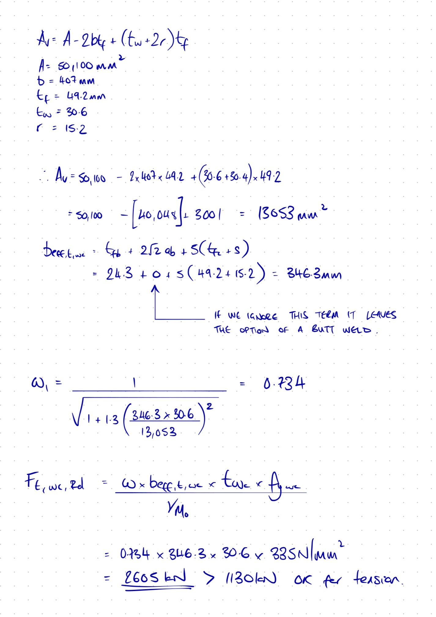
Both the tension resistance and the reduction factor are dependent on that effective length, so we hit that up first (well, actually I calculated the shear area of the web first, but we don’t need that juuuust yet). We’ll be ignoring the term with 2√2 in it, because it relates to weld, and if we elect to use a butt weld (which is perfectly possible in such heavily loaded trusses), that number should be zero. So to keep our options open, we do just that. Now we have everything we need, and the calc results in a useable web length of 346mm.
Next on the agenda is that dimensionless reduction factor, ω. All the horrid document hopping happened around here, and for the sake of sanity I’m going to skip it. The only missing variable for it is the shear area of the section (Av), which I calculated at the top of the previous section, because I was a little too eager. Our reduction factor can be seen to be 0.734. Wonderful, we’re making progress now.
With all the pieces assembled, the local check is completed simply. As I said before, when boiled down to its elements the calc is just a stress multiplied by an area, and it gives us a resistance of 2605kN. Our applied load is not the full tension in the diagonal member, just the force in the particular flange at the point of contact resolved to be vertical. Flange force can be reasonably taken as the axial in the member pro-rata to the area of the flange. Our flange force works out at 1600kN, and the resolved component is 1130kN, well below our calculated tension resistance of 2605kN. We press on, emboldened.
Next, we check for shear across the web section, and then combined shear and axial in the boom. Let’s recall the diagram where I scrawled on a rough shear force diagram:

This is just a crop from the larger calc above
In round numbers, the shear force at the leftmost flange is 1130kN (the flange force as a point load), then the shear varies up by another 855kN (the web force as a uniformly distributed load), then at the middle flange there are equal and opposite flange forces of 1130kN, so we assume the max shear force is 1130kN + 855kN = 1985kN before the shear force diagram tails back off to zero to the right.
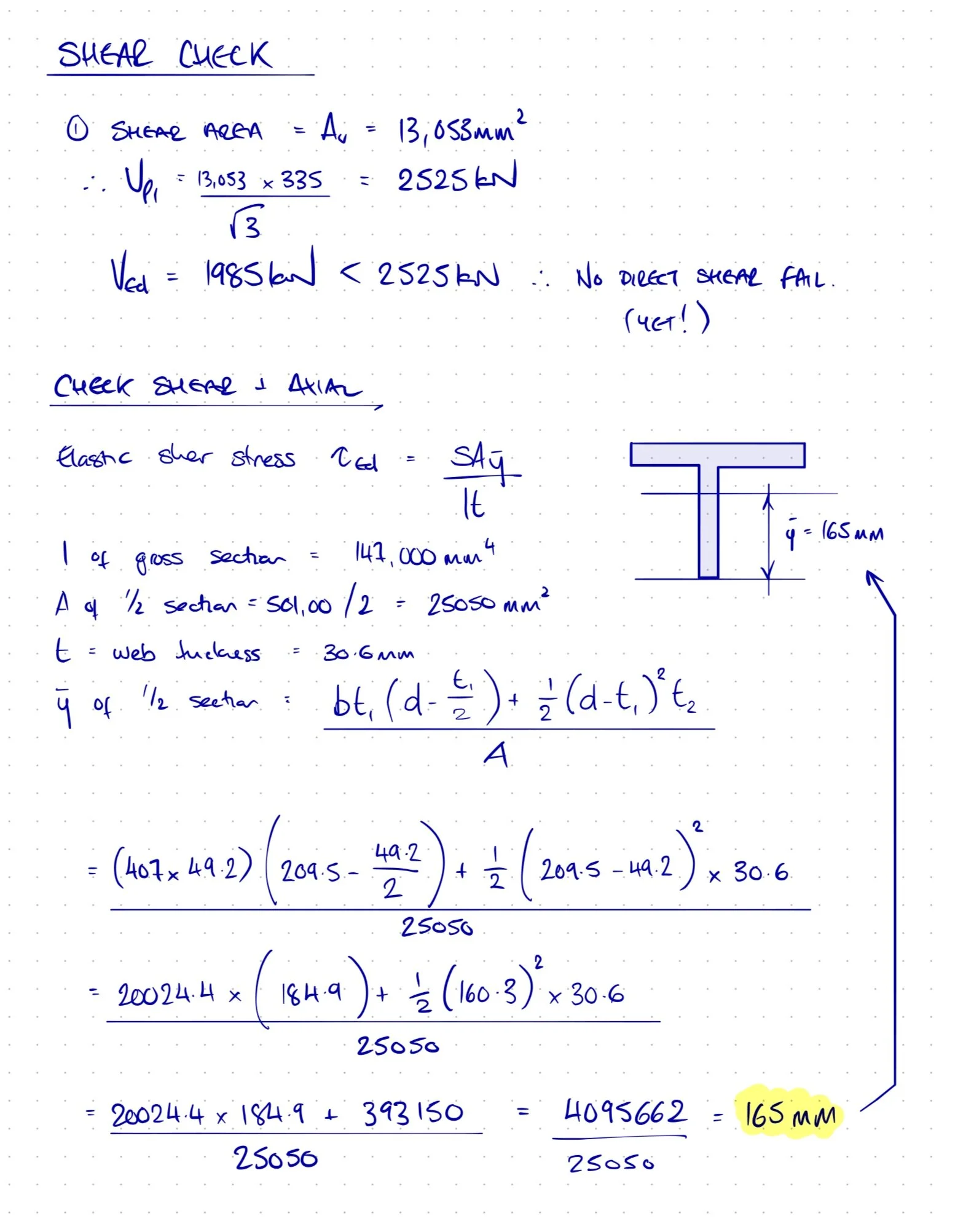
The first quick and easy check is for shear alone across the web’s shear area. We calculated the shear area (Av) before when we were doing the dimensionless reduction for the web tension, so that’s a gimme. Shear resistance is the shear area multiplied the yield strength over √3, and the force to resist is that 1985kN drawn on the shear force diagram from before. We can see that the applied force 1985kN is less than the resistance of 2525kN, so on the face of it we are good to continue.
At this point though, we really should be starting to worry about the high shears present: we can see that the section is at about 80% of its shear capacity, which should definitely set alarm bells a-ringing because we also know from the initial assumptions that the boom is also at 75% of its axial capacity. It would be sensible to expect that a combined shear and axial check will not yield good news for our member.
The final chunk of calcs on the page included above are mostly dedicated to finding the elastic shear stress, τEd. When David Brown was giving the CPD he helpfully pointed us to the Blue Book to get the value of y-bar for Tees cut from UCs. What he failed to mention was that the book only has values for Tees up to and including those cut from 305x158 UCs, and so because of the sheer massiveness of our boom we have to resort to hand calcs to get y-bar. Ok, I did have a good time doing that little calc though, so all is forgiven David.

Ouch.
So, having calculated our elastic shear stress (182N/mm²), we simply Von Mises that together with our assumed axial stress of 0.75 and we see …
Oh dear. It’s out by quite a way. 44% over-stressed. Looks like we will have to investigate stiffening that web to bring down the elastic shear stress.
Like before, the full CPD then ran through the more interesting aspect of web stiffening plates, and their limitations. Of particular note: it doesn’t matter how much additional plate you weld to that web, you can only ever take the benefit from the section’s original web thickness again, and no more. In my case, I could take the benefit of an extra 30.6mm of web plate, but no more.
For my part, I again guessed some plate sizes and weld sizes and passed those onto estimating. In all honesty, the weld size to the web plate and the preparation of the plate for fitting over the root radius of the UC are the important factors from a cost perspective, rather than the thickness of the plate itself, so again I just used my judgement rather than spend any more time on hand calcs, as interesting as these were.
So, there we are. Whilst the initial image gave away the required stiffener in the vertical 254UC, it did not spoil the surprise that a 356x368x393 UC still requires some web plates where large forces combine, despite having a THIRTY MILLIMETRE THICK web.
Ok, so maybe let’s not do that one all over again…