Prelude part one - a rough guide to bending theory
Before I get into one the meatiest topics I want to discuss, connection design, I first need to explain the basics of beam bending. This is going to be an abridged lesson in two parts, and I aim to explain everything with only a scant reliance on maths. If I do this correctly, you shouldn't even notice the maths at all. Fair warning to engineers, I will very much butcher and simplify some concepts to make them approachable to all.
Defining bending
I imagine most people are happy with understanding what it is to bend something. For instance, you might grab a ruler with a good grip at both ends and rotate your wrists resulting in a bent ruler. You might imagine a plank spanning between two rocks in a stream with a gleeful child bouncing right at the midpoint. The plank bends as the child lands and springs back to aid her next ascent.
That's a great start, but how do you truly define it? Let me explain.
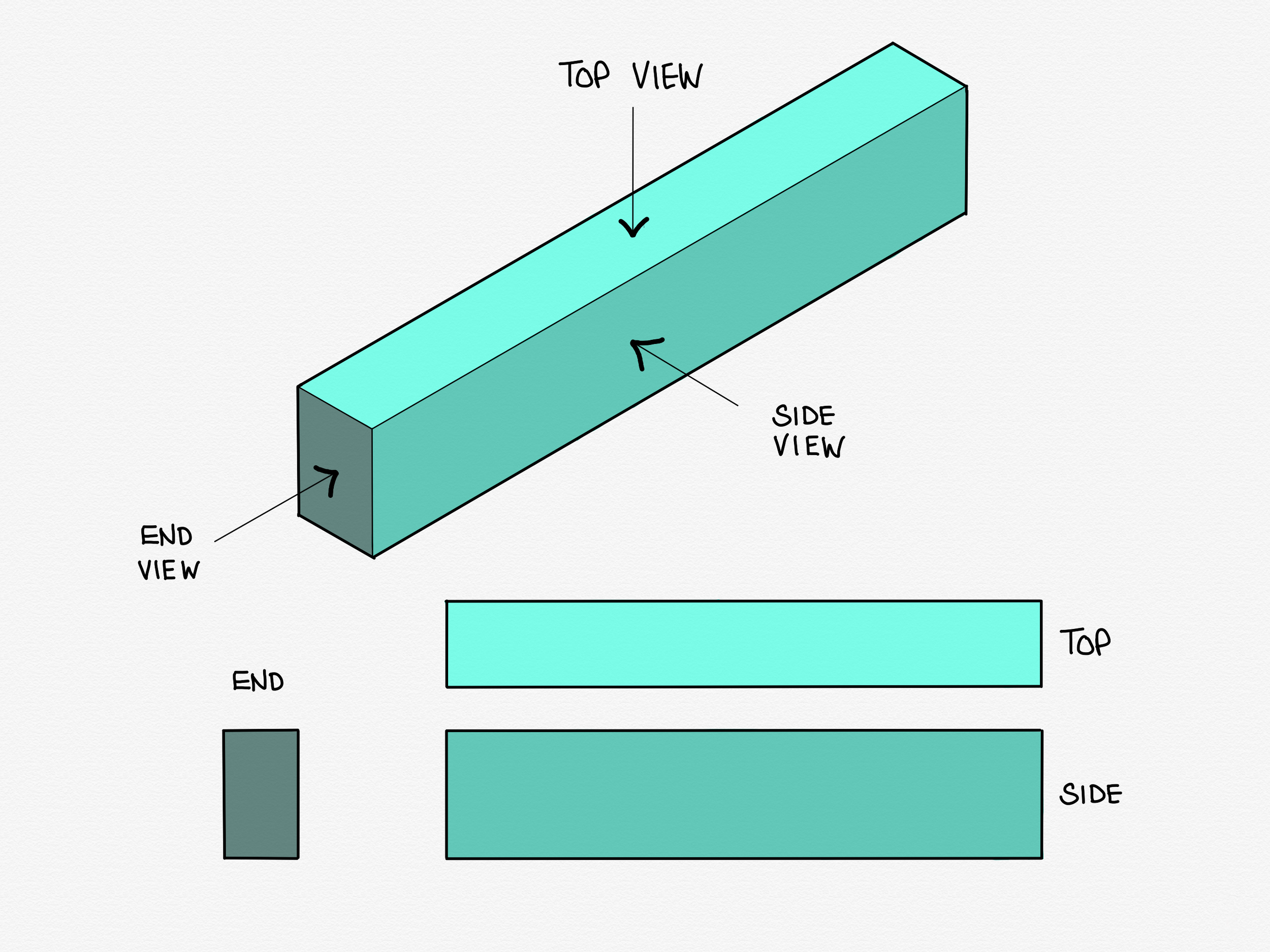
I want you to imagine a chunky, longish oblong shape like in the illustration below, and imagine it is made of sponge. I'm going to refer to this from now on as our beam. It's important to always keep in mind that our beam is a 3 dimensional object, but almost all the drawings from now on will be of the side views or end views.
Now we're going to bend our beam and have a look at what effects this has. To do this, we're going to support it at either end on something that allows those ends to rotate freely, and apply an imaginary weight to the mid-point.
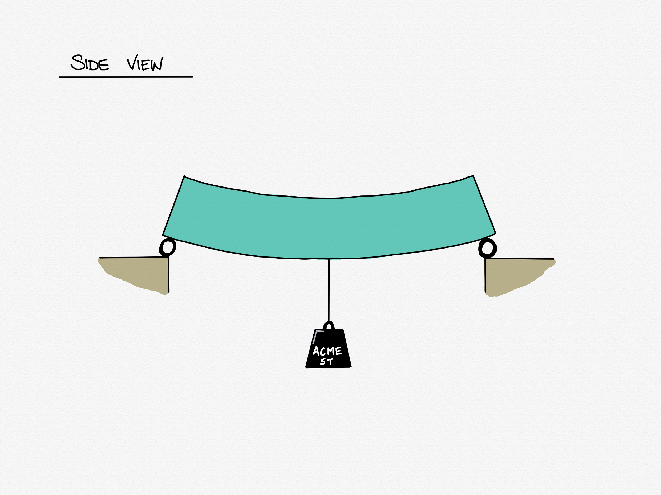
Ok, so this is what we've got. Unsurprising right? The beam is bent by the weight hanging off its middle. This is what we call the deflected shape of the beam. In this case, the beam is bending downwards, which has the technical term (I kid you not) sagging. The opposite case, when a beam is caused to bend upwards, is called hogging. I promise you it's important to have words for both of these, but that's related to a lesson for another day.
To help us understand the effect that the bending is having on the beam, I'm first going to draw a line right through the mid point of our beam along its length, and a ghost image of its unbent former self behind.

Now it's time to take a look at our spongy beam and ask ourselves the ultimate scientific question: "what can we observe?"
If we take a close look, we can see that the bottom of the beam has actually stretched out a little, and the top of the beam has squashed in. This may not sound like a particularly thrilling observation, but it allows us to define a good deal of what's going on in any beam in bending, not just our spongy little friend here.
Given that our sponge beam is uniform in shape and material, we can make some simple deductions.
- If the top half of the beam is getting squashed, and the bottom half is being stretched, at some point the material of the beam must change from being squashed to being stretched.
- Our sponge beam is uniformly spongy, so a good guess would be that it swaps from squash to stretch halfway through the beam.
- If you're on the ball, you may have already deduced that the line I drew through the middle of the beam represents the point where squash meets stretch. In fact, at the line, the beam is neither squashed nor stretched, it is perfectly unmoved. This line has a special name - The Neutral Axis.
This is good - we're making progress. Before I take us to the next step, we're going to move away from the words squash and stretch and use their engineering terms: Squash, we call compression; stretch, we call tension. Both of these we can collectively call stresses, and each of these two is the opposite of the other.
Ok, now onto some further deductions: For now, let's just think about the mid-point of the beam, that is, the point along its length from which we hung the weight.
- If the neutral axis represents a line through the beam where there is nether tension nor compression, we can say that there is zero stress along that line.
- If the top of the beam is in some amount of compression, and the bottom is in some amount of tension, but there is no stress at all halfway between, we can infer that the compressive and tensile stresses get higher the further away they are from the neutral axis.
- It then follows that the highest stresses are at the very top and the very bottom of the beam.
Let's smash open the beam and take a better look at what's going on inside:

Now we're going to see what we call a 'section through' the beam, which is a quick way of saying "we are going to imagine you can literally slice/explode whatever we are interested in open and look at its insides". We're doing that so we can think about how the stresses vary from top to bottom.

Now don't freak out. I realise I've come in strong with a fairly busy diagram, but give me moment to explain before your eyes gloss over. All this shows is what we already know. The stress in the beam varies from the highest tension at the bottom, to zero at the neutral axis, to the highest compression at the top.
In the most simplistic way, this is how we define bending - bending is directly related to the highest values of tension and compression stress caused by whatever is bending the beam at any given point.
Ok, so far we have established that there is some amount of stress at one point: the middle of the beam. For now, it doesn't even matter what that amount is. What we are going to be concerned with in the next article is how that bending stress varies along whole length of the beam, because what happens when we get to the very ends of the beam is the whole reason I've written everything so far.
Thanks for reading this far - I really appreciate it. If you have any comments or corrections, you can get in touch with me via email (martyn@martynpie.com) or @martynpie on Twitter.