Bonus Content - Paper Aeroplanes!

When I was about 10 or so, my grandma once gave me a copy of a magazine; I'm fairly sure it was a Reader's Digest. Within those pages were the instructions to make a paper aeroplane - I vaguely recall it was some sort of competition winner or record holder. I committed the design to memory, and ever since it's been my go-to design for airborne paper hijinks.

I spent a futile 15 minutes this weekend trying to find some record of it online with the idea of first showing it to some family who were staying this weekend, then secondly of putting it up on Twitter. However, my Google-Fu let me down, so I decided I'd draw up a set of instructions of my own and post them here instead.

If anyone who sees this can find any proper attribution for the design, I'll happily update to include it, but for now, here we go...

Aeroplane - 01.png
Aeroplane - 02.png
  1. Fold down one of the top corners to its opposite side, make the crease sharp, then unfold.
  2. Repeat for the other corner.
  3. Fold horizontally back over, make a nice sharp crease, then unfold again.
  4. Bring the points all labelled 3 together, which should collapse all the pink area into the shape of the blue triangle.
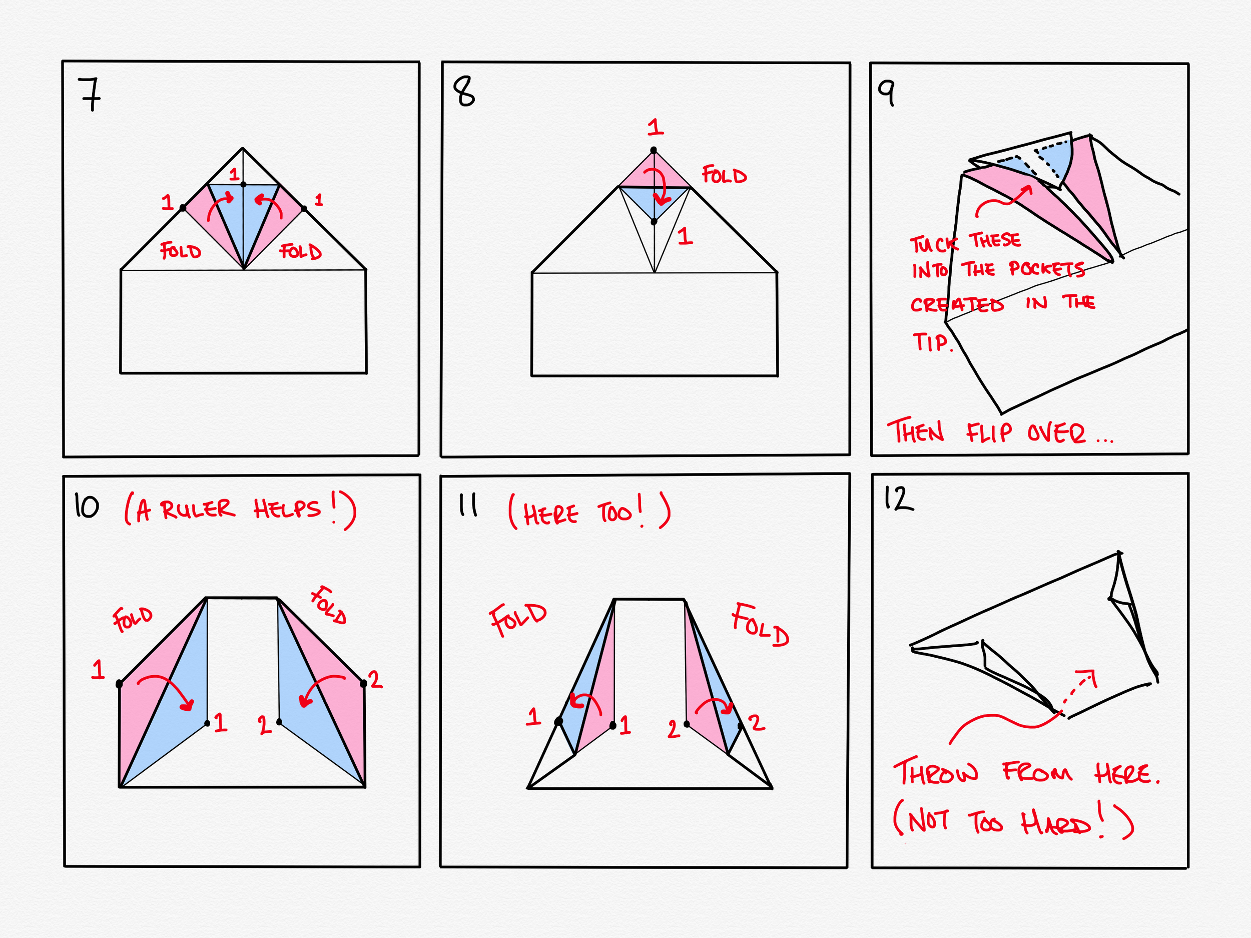
  5. Fold up the loose flaps into the shape shown.
  6. Fold in the the corners again to create a kite shape.
  7. Step 7 I now realise (much too late to change it) is inexplicably a copy of step 6. You may safely ignore it and move onto step 8.
  8. Fold down the point as shown.
  9. This is the tricky bit. Unfold the pink parts - the top ones only - then tuck them into the pockets you find in the tip you folded over on step 8. You might need to bend them a little to get the in, but once you've got them slid in and flattened down then the whole thing will hold itself together solidly.
  10. Flip the paper over so you're now looking at the top of the plane - all the work you've done so far was on the underside - then make the folds as shown; these will be winglets. To get these folds exactly right it helps to use a ruler*.
  11. Fold the edges of the winglets back on themselves and then give them a gentle tug so they don't lie too flat to the body of the plane.
  12. Hold it by finger and thumb on the little pocket on the underside, and give a throw! It works best if you give it more of a deliberate straight push (a bit like a dart) than a throw.

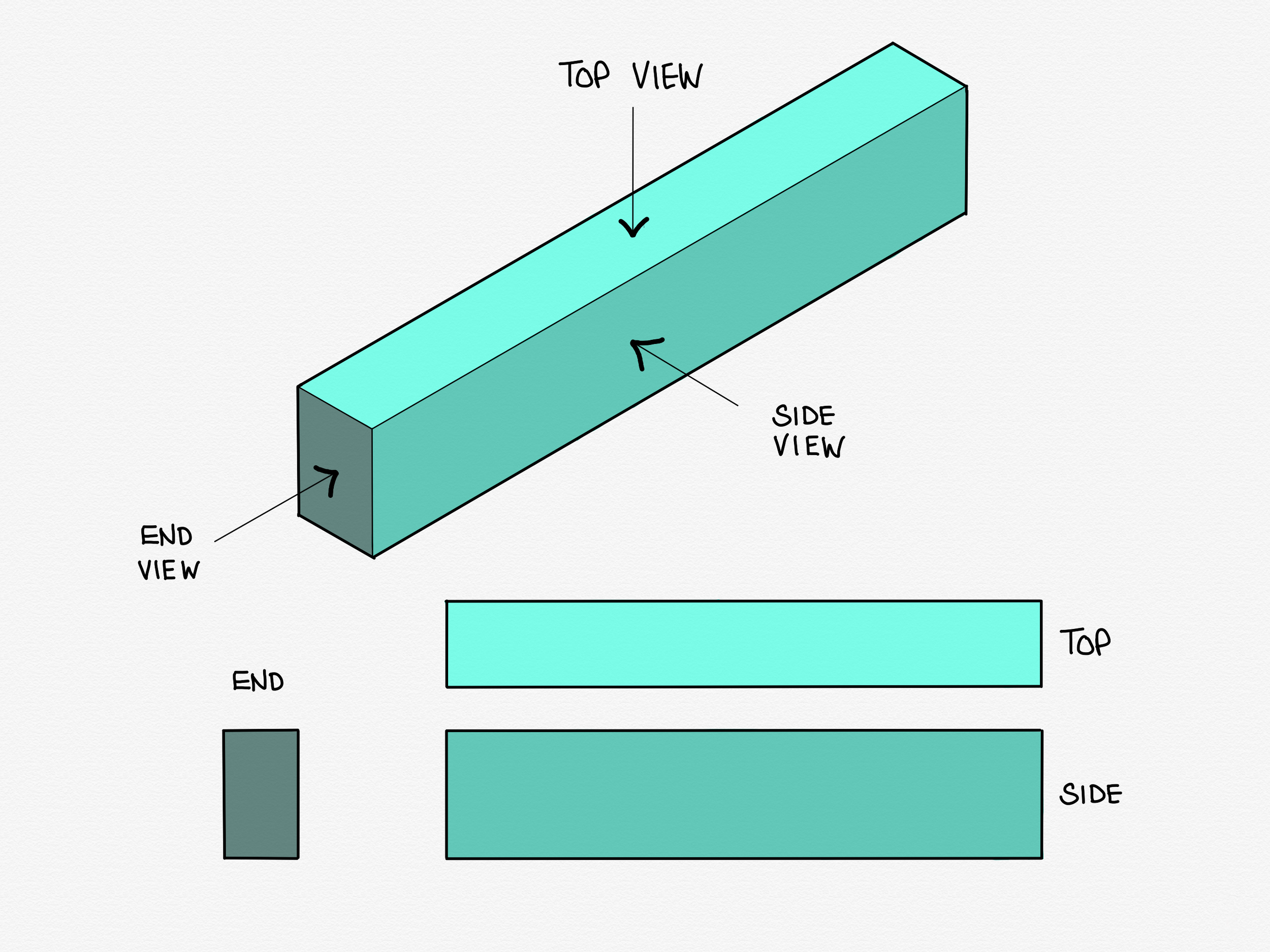
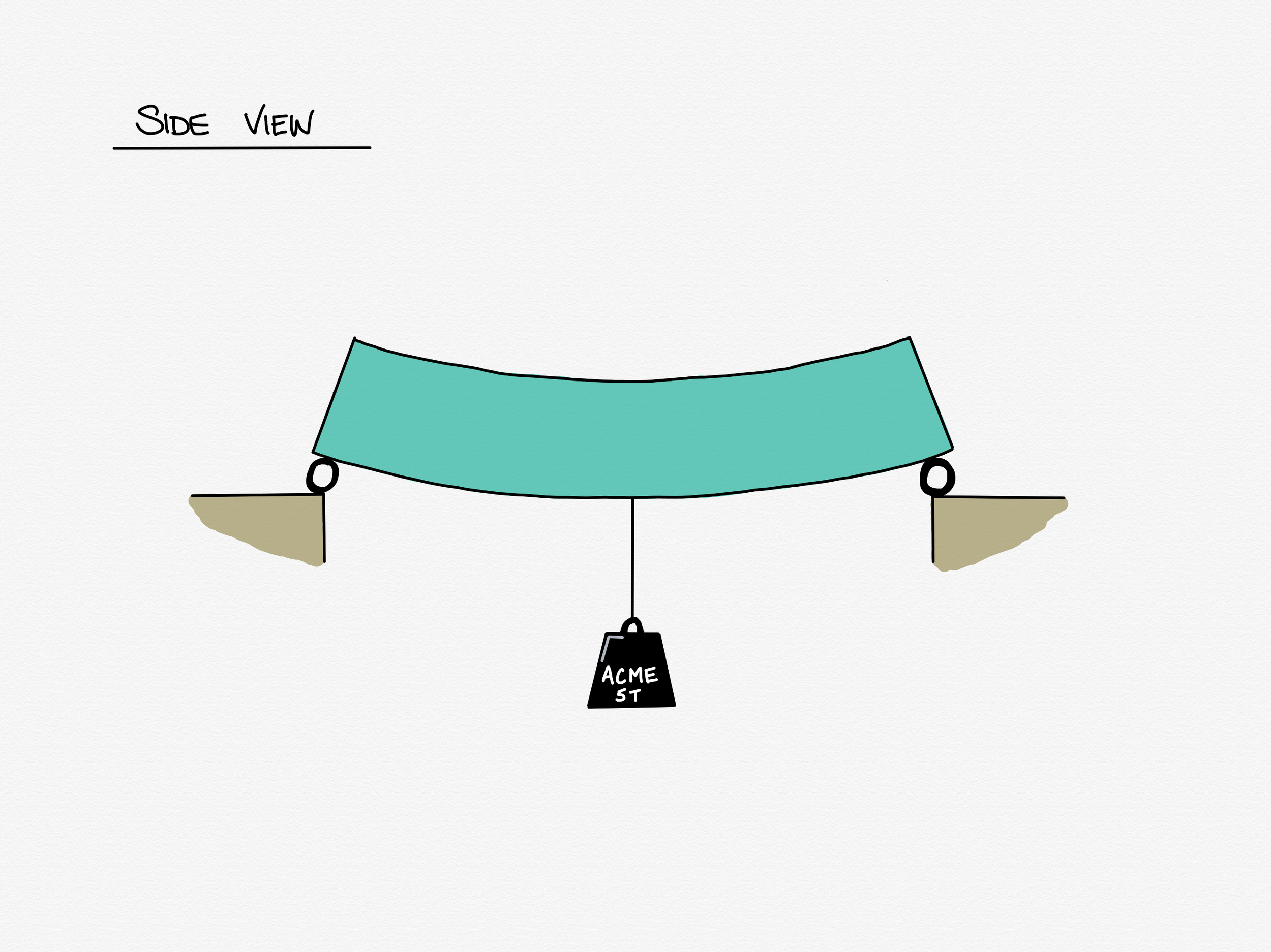
Note: Don't bend it or fold it in half - the whole thing is a wing.

If you want, you can post photos your attempts to follow my hastily compiled instructions to twitter and mention me on @martynpie or you can be a crazy person and email me at martyn@martynpie.com

*I know, I know, rulers again. Sorry.

Prelude - part II

Today we pick up where we left off last week on our whistlestop tour of beam bending.

At the end of the last week we established that:

  1. If we apply a weight to a beam, it deflects downwards.
  2. The deflection causes the top half of the beam to compress, and causes tension in the bottom half.
  3. At the mid point of the beam there must be some amount of stress. 

Today, we are going to derive what happens all the way along the beam by paying particular attention to the very end points. We are in fact, going to begin by leaping right in with what happens at the ends of our particular beam.

If you recall the last post, I specifically said the end supports in our first example must allow the beam to rotate. There are both good practical and good mathematical reasons for this stipulation; the former we will cover another day, and the latter we are going to skip right over. For today we are going to start by accepting that the ends of the beam are allowed to rotate and that we call this a pinned support. Then we will consider what that in turn must mean for our bending stress at the ends of the beam. 

Pinned Supports

To explain why we have pinned supports and what they are I’m pretty excited to bring out the structural engineer’s most trusty, yet utterly unglamorous assistant to aid with the explanation: The ruler. Yes, the ruler. That 30cm shatterproof slice of secondary school nostalgia (but not those hinged ones that fold in half, sorry, but they were always rubbish) is every structural engineer’s best desk buddy. 

Behold, our beam as represented in compass-point graffitied, hi-res digital art!

IMG_0532.PNG

I know. Thrilling right? No really, the humble ruler truly is a useful bit of kit when trying to understand bending, I promise.

If you don’t have a ruler to hand to play along, I want you to imagine you are holding a ruler as drawn above, otherwise, go root around in your pencil case then come straight back.

Ready now? 

Great - let’s go. Balance the ruler on your fingers as shown in the drawing. Now keep your left hand motionless but raise and lower your right hand while concentrating on what you feel with your left fingertip where it supports the ruler. You feel the ruler rocking on your finger? It’s rotating freely. No matter how quickly or how forcefully you move your right hand you won’t change that fact - the ruler will always spin about the finger of your left hand. It sounds trite, but this is the perfect way to think of a pinned support.

Now why do we want pinned supports? The simple fact is that bending stress can never occur at a pin. Without something to actively resist the ruler, any bending you apply disappears at the pin. Try it yourself with your ruler! The simplest way to demonstrate it is as below:

Prelude Part 2 - 2018-05-03 20.51.44.png

You create a pin support like before with your index finger of one hand, let a decent length of ruler project past your finger, and force the beam to bend with your other hand. You can see that between the support (your finger) and applied rotation (your fist) the ruler bends, but at and after the pin the ruler is completely unbent - perfectly straight in fact, that is unless you’ve been abusing your ruler beforehand and if that is the case, frankly I can offer you no help there. 

The lesson to learn from this exercise is that bending, as we have defined it, cannot exist at a pinned support. Now, if bending cannot exist, the stresses - our tensions and compressions from the previous lesson - cannot exist either. If you stop and think about this we can say that we have now defined along our beam three points at which we have some idea of the bending stresses.

  1. We have the left support, where the bending stresses are zero.
  2. We have the middle of the beam (where the load was applied) where the stress is ... something.
  3. We have the right support, where the bending stresses are zero.

Let's put that on a drawing shall we?

Prelude Part 2 - 2018-04-23 11.56.28.png

Again, don't fret about the unfriendly diagram - just like last time it shows us what we already know. The pink shape I've sketched over the beam shows us what we have derived: there's no stress at either end, and some amount of stress in the middle.

I have made (and will gloss over) two assumptions .

  1. I have shown a linear distribution of bending stress - that is the stress varies in a straight line from 'something' at the middle to nothing at either end giving us a distinct triangular shape.
  2. I have assumed that the biggest stress occurs in the middle, where the load is.

I also know that I've left the actual amount of bending stress somewhat loosely defined in the middle there as 'some' stress, but frankly you've suffered enough if this is all new to you. Trust me when I say that there is a lot of unavoidable (but very pretty) maths to get to the true answer, which probably isn't even a topic for another day - it will take a lot to make that interesting enough to read for pleasure. 

But there it is - from nothing but a bit of common sense and a piece of plastic we've derived a way of showing bending stress distribution under a point load, and at the same time learned about pinned supports.

Next time I write on this topic, we can start getting into connections proper.

As always, comments and corrections are welcome either via email (martyn@martynpie.com) or via twitter (@martynpie).

Prelude part one - a rough guide to bending theory

Before I get into one the meatiest topics I want to discuss, connection design, I first need to explain the basics of beam bending. This is going to be an abridged lesson in two parts, and I aim to explain everything with only a scant reliance on maths. If I do this correctly, you shouldn't even notice the maths at all. Fair warning to engineers, I will very much butcher and simplify some concepts to make them approachable to all. 

Defining bending

I imagine most people are happy with understanding what it is to bend something. For instance, you might grab a ruler with a good grip at both ends and rotate your wrists resulting in a bent ruler. You might imagine a plank spanning between two rocks in a stream with a gleeful child bouncing right at the midpoint. The plank bends as the child lands and springs back to aid her next ascent.

That's a great start, but how do you truly define it? Let me explain.

I want you to imagine a chunky, longish oblong shape like in the illustration below, and imagine it is made of sponge. I'm going to refer to this from now on as our beam. It's important to always keep in mind that our beam is a 3 dimensional object, but almost all the drawings from now on will be of the side views or end views.

Prelude Part 1 - Isometric.png

Now we're going to bend our beam and have a look at what effects this has. To do this, we're going to support it at either end on something that allows those ends to rotate freely, and apply an imaginary weight to the mid-point.

Prelude Part 1 - 2018-04-19 11.08.46.png

Ok, so this is what we've got. Unsurprising right? The beam is bent by the weight hanging off its middle. This is what we call the deflected shape of the beam. In this case, the beam is bending downwards, which has the technical term (I kid you not) sagging. The opposite case, when a beam is caused to bend upwards, is called hogging. I promise you it's important to have words for both of these, but that's related to a lesson for another day.

To help us understand the effect that the bending is having on the beam, I'm first going to draw a line right through the mid point of our beam along its length, and a ghost image of its unbent former self behind.

Prelude Part 1 - Def Shape + Ghost + NA.png

Now it's time to take a look at our spongy beam and ask ourselves the ultimate scientific question: "what can we observe?"

If we take a close look, we can see that the bottom of the beam has actually stretched out a little, and the top of the beam has squashed in. This may not sound like a particularly thrilling observation, but it allows us to define a good deal of what's going on in any beam in bending, not just our spongy little friend here.

Given that our sponge beam is uniform in shape and material, we can make some simple deductions.

  1. If the top half of the beam is getting squashed, and the bottom half is being stretched, at some point the material of the beam must change from being squashed to being stretched.
  2. Our sponge beam is uniformly spongy, so a good guess would be that it swaps from squash to stretch halfway through the beam. 
  3. If you're on the ball, you may have already deduced that the line I drew through the middle of the beam represents the point where squash meets stretch. In fact, at the line, the beam is neither squashed nor stretched, it is perfectly unmoved. This line has a special name - The Neutral Axis.

This is good - we're making progress. Before I take us to the next step, we're going to move away from the words squash and stretch and use their engineering terms: Squash, we call compression; stretch, we call tension. Both of these we can collectively call stresses, and each of these two is the opposite of the other.

Ok, now onto some further deductions: For now, let's just think about the mid-point of the beam, that is, the point along its length from which we hung the weight.

  1. If the neutral axis represents a line through the beam where there is nether tension nor compression, we can say that there is zero stress along that line.
  2. If the top of the beam is in some amount of compression, and the bottom is in some amount of tension, but there is no stress at all halfway between, we can infer that the compressive and tensile stresses get higher the further away they are from the neutral axis.
  3. It then follows that the highest stresses are at the very top and the very bottom of the beam.

Let's smash open the beam and take a better look at what's going on inside:

Prelude Part 1 - Who needs a section.png

Now we're going to see what we call a 'section through' the beam, which is a quick way of saying "we are going to imagine you can literally slice/explode whatever we are interested in open and look at its insides". We're doing that so we can think about how the stresses vary from top to bottom.

Prelude Part 1 - 2018-04-20 19.08.12.png

Now don't freak out. I realise I've come in strong with a fairly busy diagram, but give me moment to explain before your eyes gloss over. All this shows is what we already know. The stress in the beam varies from the highest tension at the bottom, to zero at the neutral axis, to the highest compression at the top. 

In the most simplistic way, this is how we define bending - bending is directly related to the highest values of tension and compression stress caused by whatever is bending the beam at any given point.

Ok, so far we have established that there is some amount of stress at one point: the middle of the beam. For now, it doesn't even matter what that amount is. What we are going to be concerned with in the next article is how that bending stress varies along whole length of the beam, because what happens when we get to the very ends of the beam is the whole reason I've written everything so far.

Thanks for reading this far - I really appreciate it. If you have any comments or corrections, you can get in touch with me via email (martyn@martynpie.com) or @martynpie on Twitter.

Aims, topics, and breaking your own rules.

I currently intend to keep my articles here within at least a recongisable orbit of structural engineering, and my relationship with it. I also intend to limit the number of articles aimed specifically at engineers to something like every third piece. When I do write technical articles, I will still do my best to make them understandable to anyone willing to take the time to read them.

To that end I will endevaour to adhere to a set of rules I try to always keep in mind whenever I write at work, be that in emails, reports, or letters. These were set out by George Orwell in his essay Politics and the English Language in 1946:

1. Never use a metaphor, simile, or other figure of speech which you are used to seeing in print.

2. Never use a long word where a short one will do.

3. If it is possible to cut a word out, always cut it out.

4. Never use the passive where you can use the active.

5. Never use a foreign phrase, a scientific word, or a jargon word if you can think of an everyday English equivalent.

6. Break any of these rules sooner than say anything outright barbarous.

I must confess, many professionals in the construction industry are guilty of breaking all of these rules a good deal of the time. What is accepted as a "professional" writing style is often just poor writing: it is usually flabby, overwrought, and pompous. 

I also intend to abuse the sixth rule not only with regard to my writing style, but also my content. I will definitely write about topics outside the world of structural engineering.

I do have in a mind at least a few specific topics that I would like to write about at some point, including:

- Connections

- Paperless working

- Time

- My route to professional qualification

But for now, I implore anyone reading this to go and read Orwell's essay if you haven't already. It's not very long, freely available, and eye-opening. 


Welcome

I’ve been doing the same thing, more or less, for a decade now.

When someone is kind enough to ask me what I do for a living, the range of answers I give start around the vague, innacurate, but easily digestable “I sort of design buildings”.

I’d like to take you from that sketchy description forward, to paint a picture of what I really do,

I am a Structural Engineer, but not as you probably know them, if you already have an idea of what one is.

If a person has an idea of what a Structural Engineer is, the image they would likely have in their mind would reflect a Consultant Structural Engineer; someone who works across projects in many fields. They might come to your house to advise you about a domestic extension, or do high level design of an office building, or design bridges. They would work across multiple materials; reinforced concrete, timber, steelwork, masonry or even more esoteric materials like structural glass.

Quite by accdent, I sidestepped this life in favour of specialisation.

Shortly after completing my degree I found myself working almost exclusively in structural steelwork, starting with a two-year stint at a now defunct structural steelwork fabricator in West Yorkshire specialising in Design and Build. This is where my journey into specialisation began. In the run-up to its collapse (see: Global Financial Crisis of 2007-8), I was offered a job at a small consulting practice in my home city, which I gladly took. Almost a year to the day later, a former colleage approached me to join him at another fabricator, this time in North Yorkshire, and there I have remained for the last 8 years.

The life of an engineer working for a fabricator is very different to that of a consultant, and as I write this welcome piece, I believe that difference is one of the main topics I want to explore here. It is exciting that public awareness of engineering as a whole is increasing, so I hope that I can contribute to a modest bump in the awareness of my small, and perhaps overlooked field.

The first question I must now ask myself is “does anyone care?” followed swiftly by “is this even interesting?”. The answers I give myself are “well yes, I do” and “I truly hope so” respectively. I don’t know who will be keeping score for me, but whoever they may be, I hope they are kind enough to let me down gently if I’m wrong.