Today I want to pull together a couple of threads which have been brought to mind by events which occurred a few weeks ago. I will do my best to keep the language layperson-friendly, and as such will no doubt butcher some (ok, many) structural concepts.
I have been planning since the very beginning of this blog to pick apart some of the tricky areas of overlap in design responsibilities between fabricators and consultants, and a project I have just completed design work on nicely highlights a good few of these tricky areas.
My company recently won a traditional contract with a very short lead-in. The contract was to supply a multi-storey building with a significant transfer structure* consisting of a system of trusses which in turn carry two columns from first floor right up to the roof some five storeys up. We were given just ten weeks from the point of order to requiring the first loads of steel to be erected on site. This is about six weeks short of the period we’d usually have: time was tight, and this project was complex.
*Transfer Structure: A term usually given to typically heavy-duty structure used to carry other structural elements. In this example there is a large lecture theatre on the ground floor which cannot have columns in the middle of it. In our case above the lecture theatre, hidden in the ceiling, are enormous trusses which have the columns for the rest of the building above resting on them. The trusses transfer the load from the carried columns out to the columns on the perimeter.
The David Brown
Those of you diligent engineers who fastidiously carve out time to read The Structural Engineer every month will of course have read, digested, reflected upon, and taken to heart all the advice given in this wonderful article written by David Brown of the Steel Construction Institute in their July/August 2016 issue. For those of you have haven’t already, you’re about to get a sub-standard re-hashing of great swathes of it, but presented from the figurative coal (steel?) face. I highly recommend reading Brown’s article if you are an engineer who has ever designed steel framed buildings whilst working in consultancy. Or a human being interested in reading this website for that matter.
Brown’s article has six sections, covering the following circumstances:
1. Connections with high tying forces.
2. Flange to web welds in a plate girder.
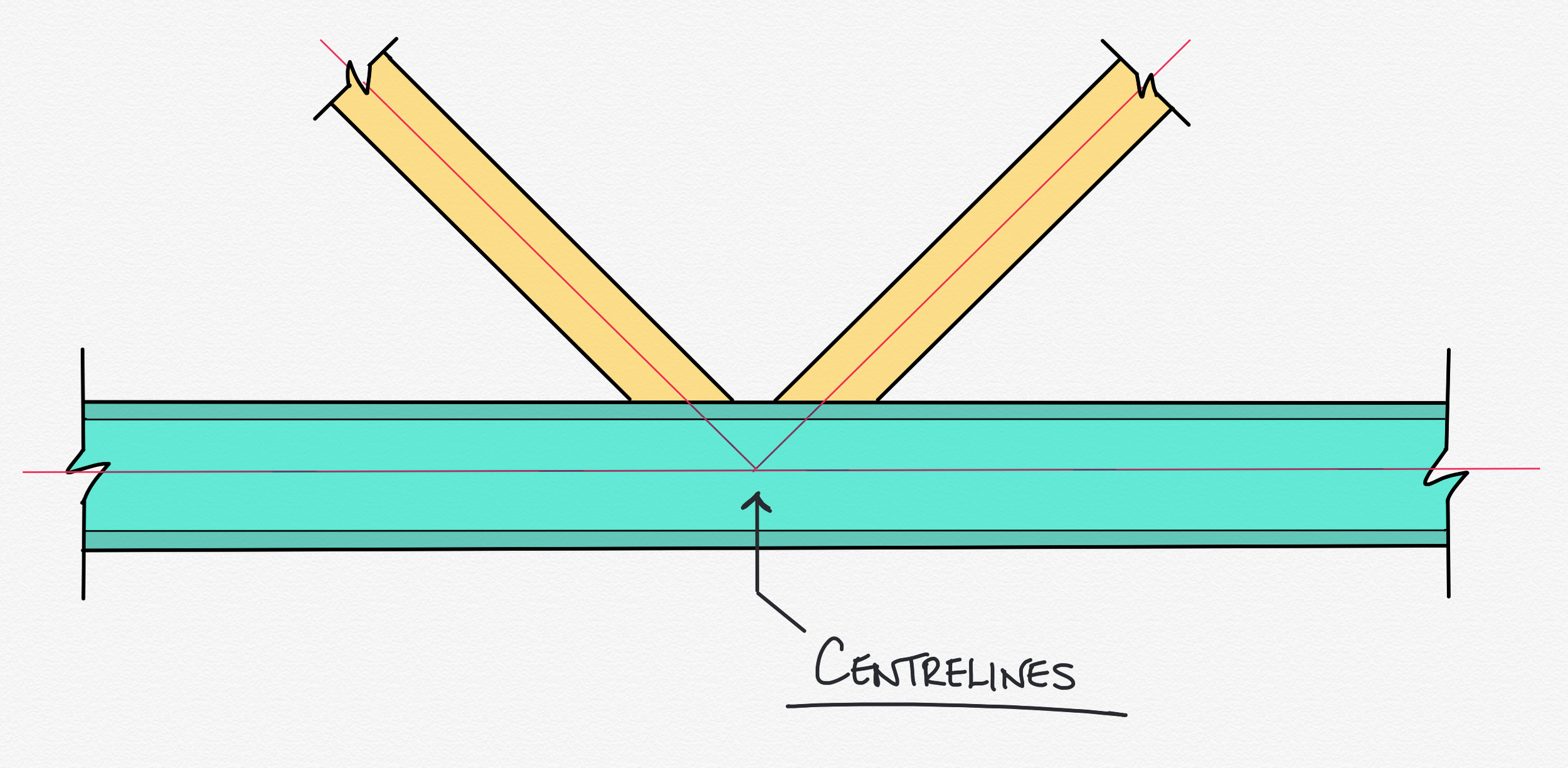
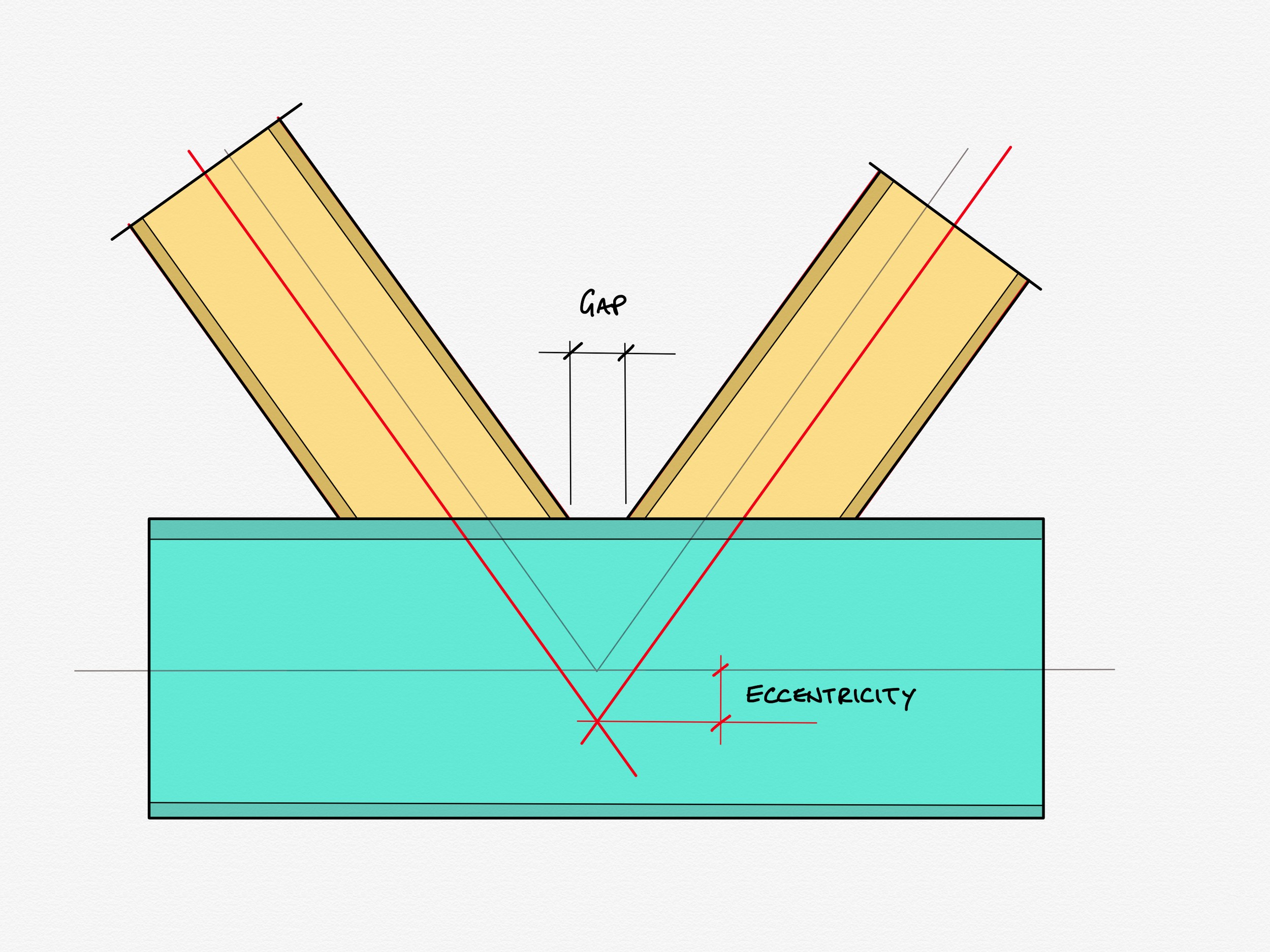
3. Joint resistance in hollow section trusses.
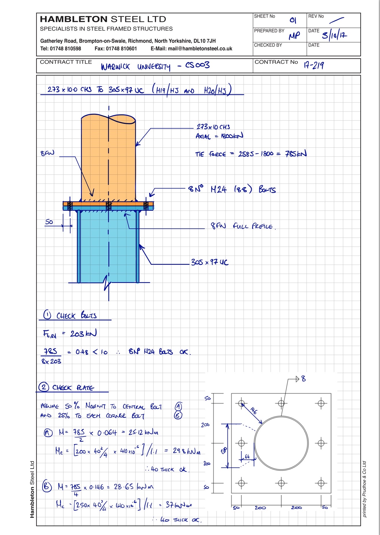
4. Holding down bolts and foundation design.
5. Nominally pinned connection invalidate the original assumption of full fixity to the column.
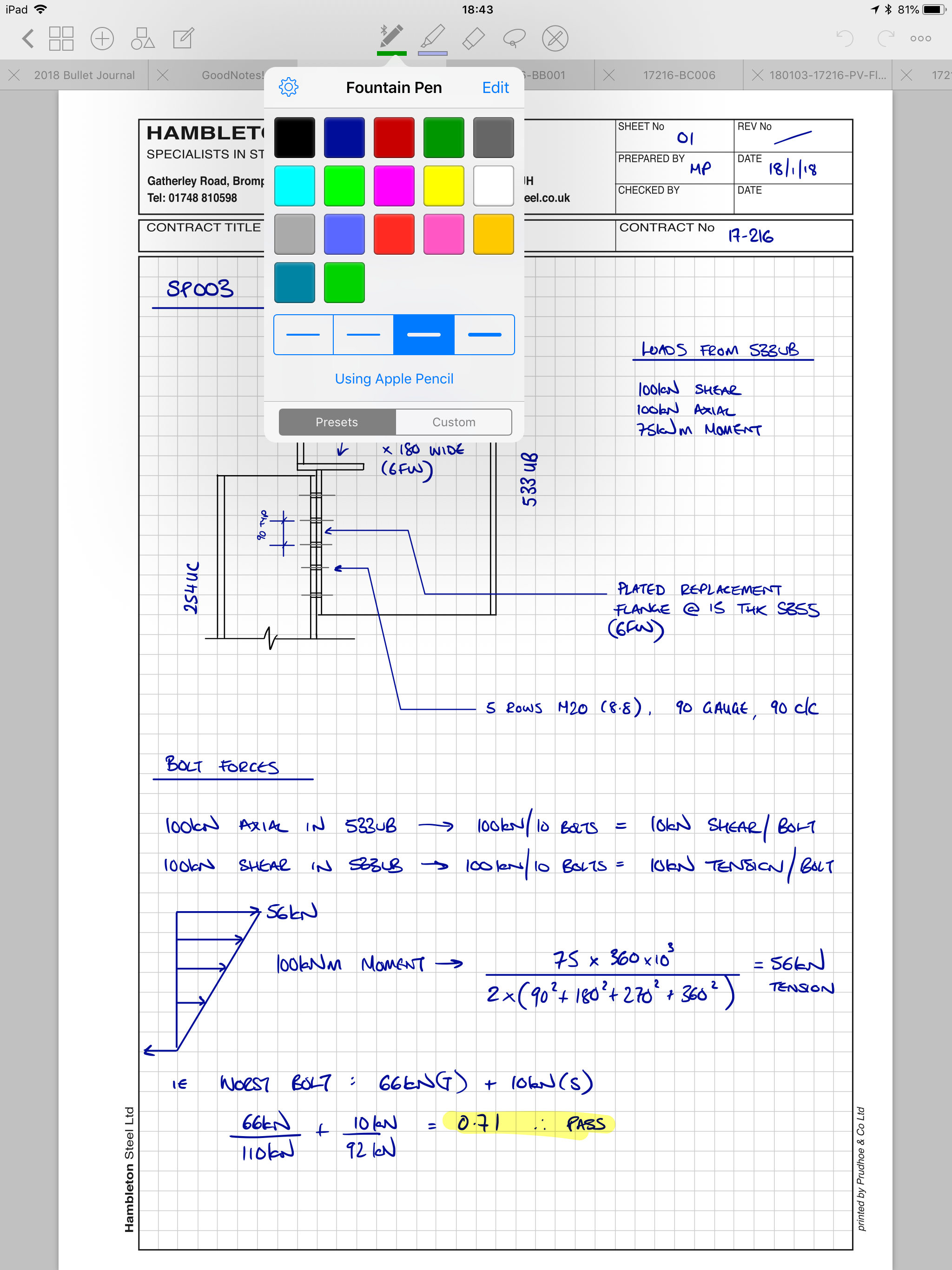
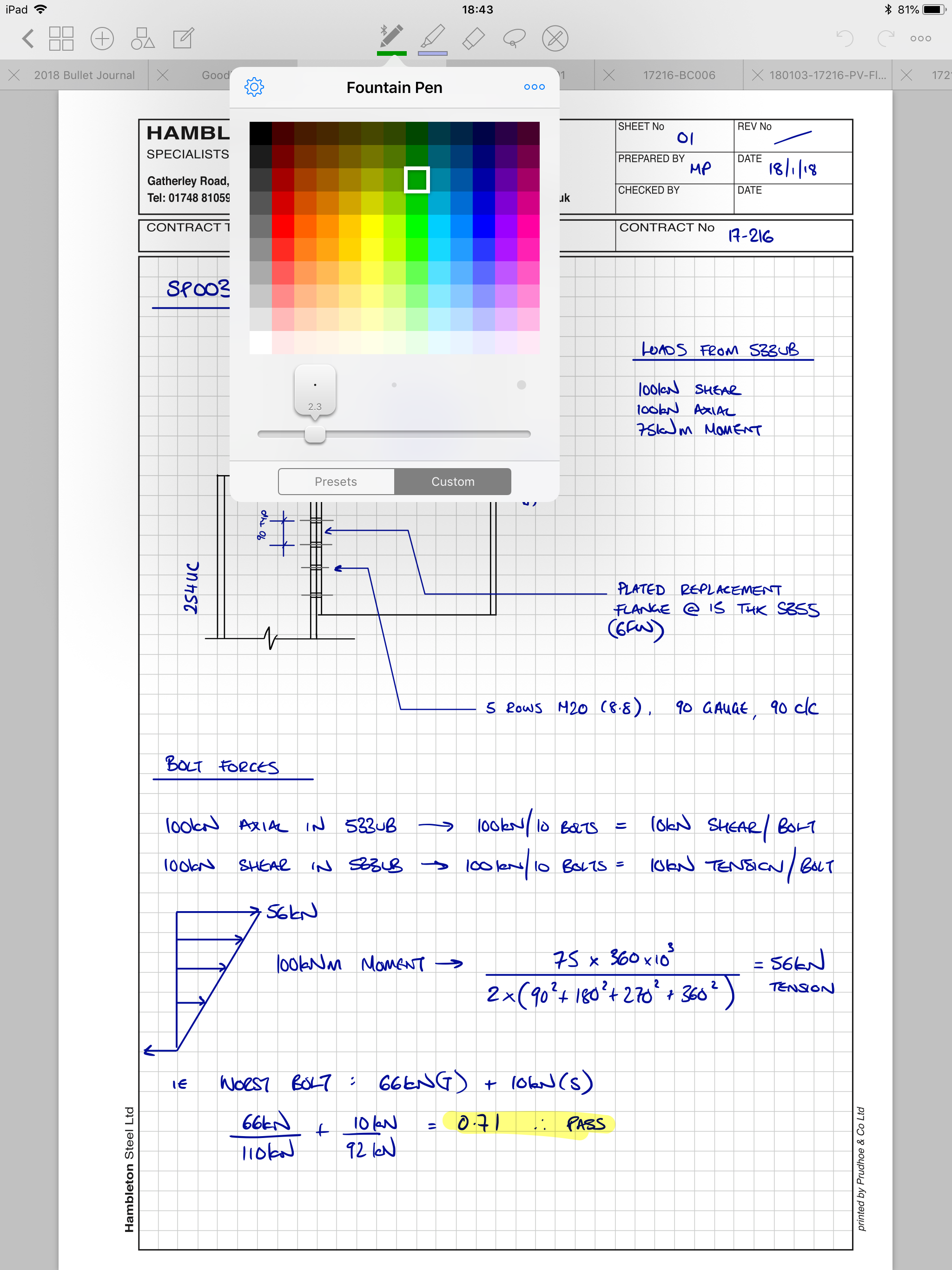
6. High shear and bending.
If any of those terms in the section titles cause you to scratch your head; fear not. We’ll be explaining as we go along.
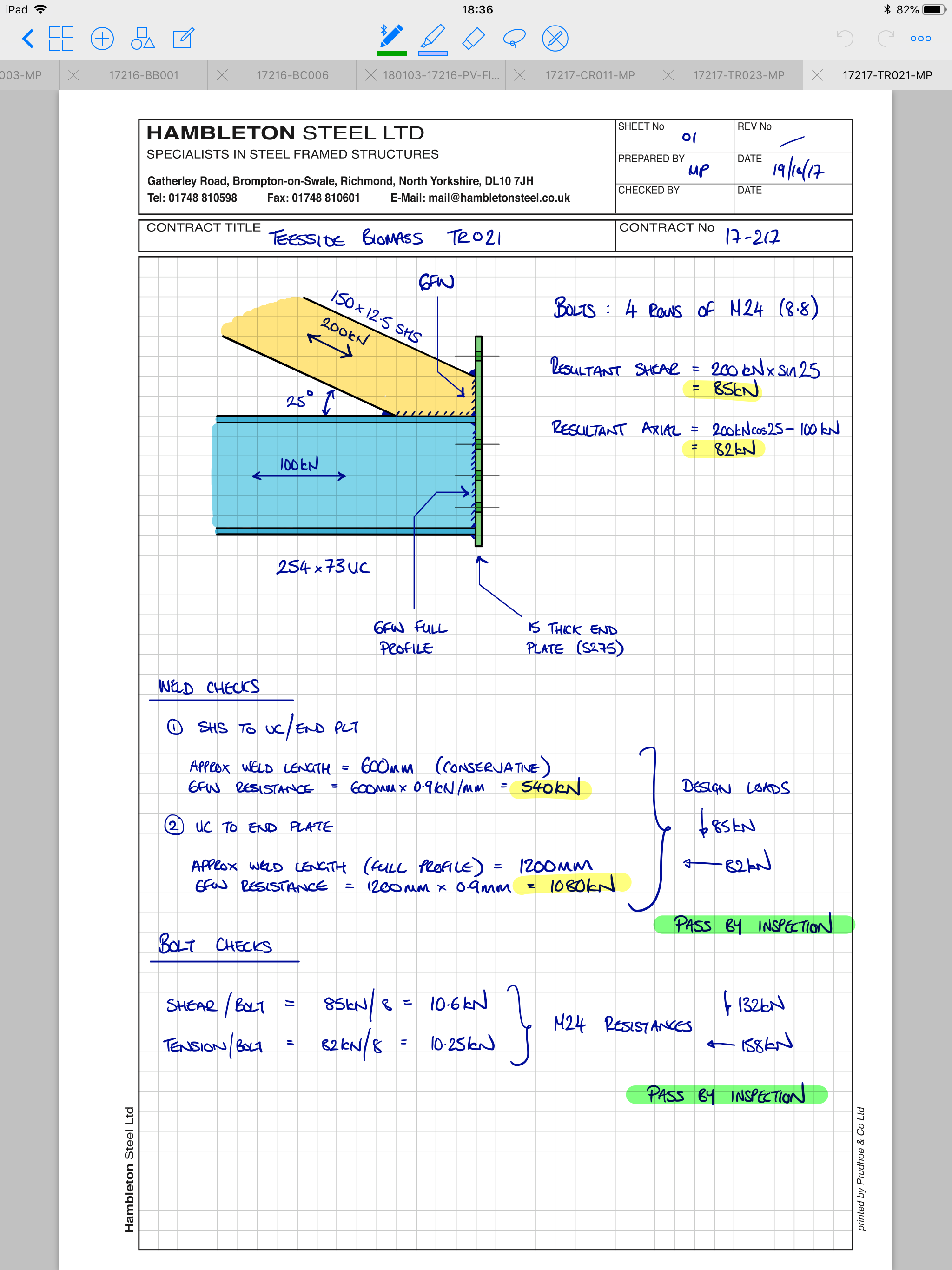
This project had instances of four out of the six situations covered by Brown’s article: connections with high tying forces, joint resistance in hollow section trusses, holding down bolts with significant shears and uplifts, and high shear and bending. In the following series of articles here, I’ll cover each in turn, explaining what they are, and how each was resolved.
To round out this introduction, I’ll give a brief explanation of the two circumstances not present on our example contract.
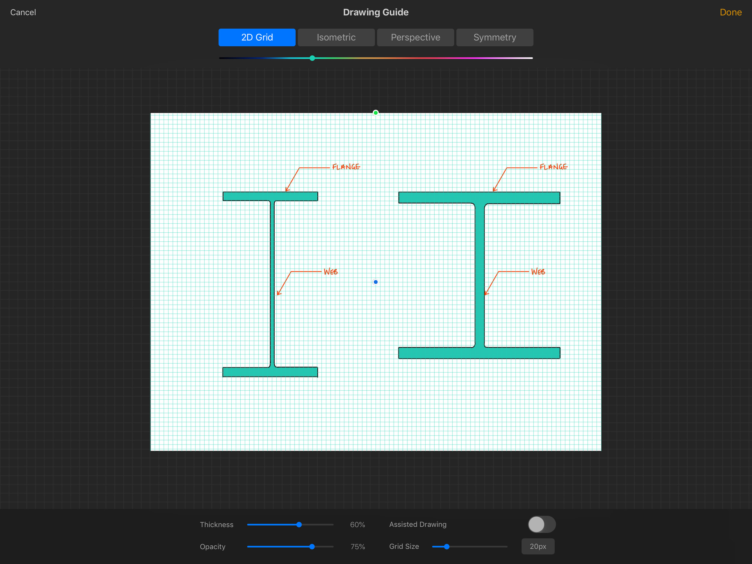
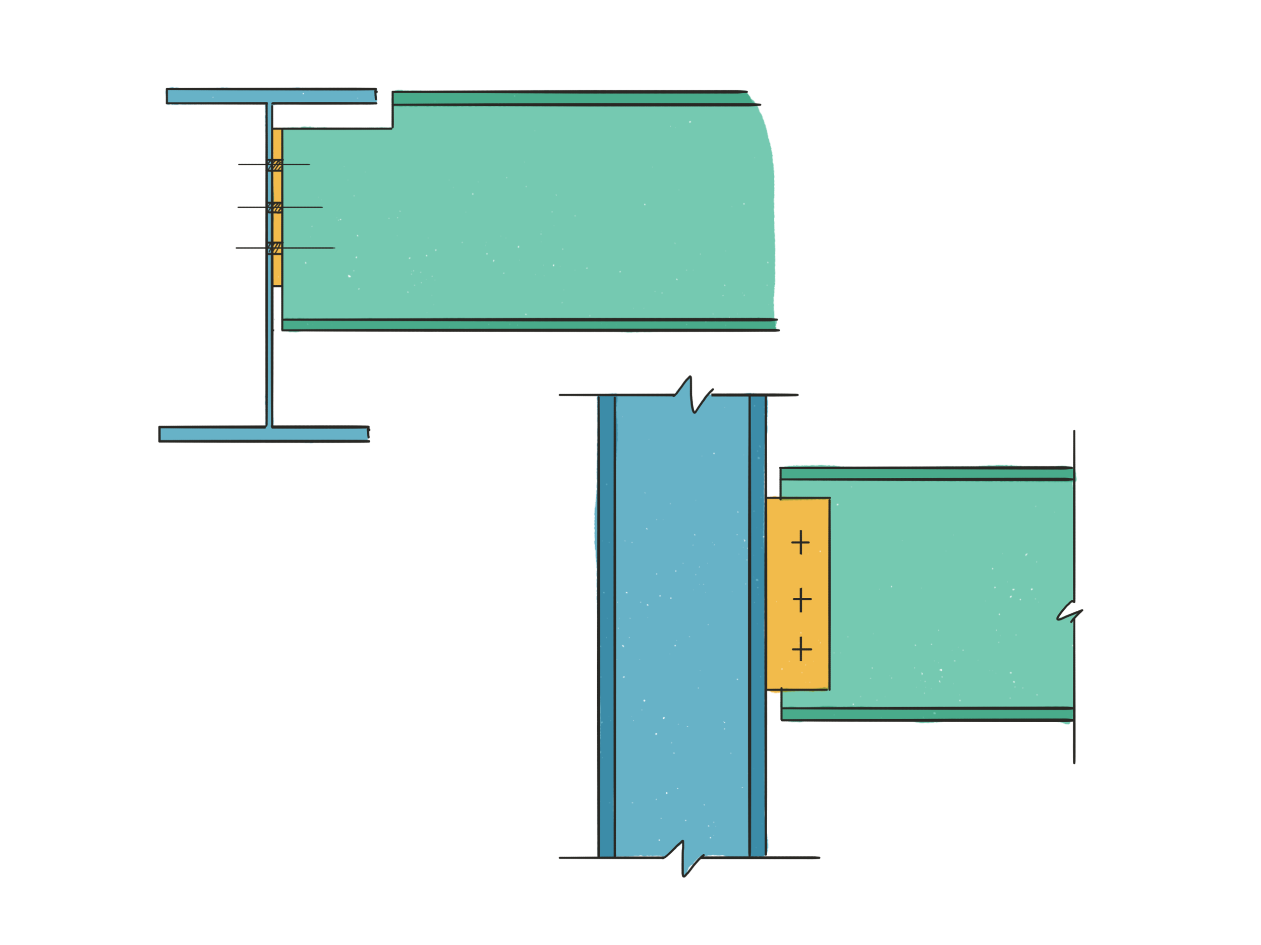
Flange to web welds in a plate girder
Of all the sections in Brown’s original piece, this is by far the shortest (just 23 well chosen words). A plate girder is beam or column not rolled as a single lump (imagine rolled sections coming out of a very hot, and very large sausage machine); instead a plate girder is made out of three flat plates which are later welded together into an I or H shape by man or machine.
The conflict between consultant and fabricator is over which of the parties designs the welds between the plates - that is the welds that hold the beam together. I don’t know how conflict over this responsibility ever became common: the line is clear. The person who designs the beam designs those welds: they are not connection design, they are integral to member design.
In terms of my own experience, it is common for consultants to deem this as part of a fabricator’s remit, and without fail we send it back to the consultant, occasionally with a link to Brown’s article.
Nominally pinned connection invalidate the original assumption of full fixity to the column.
That’s a bit of a mouthful isn’t it? Breaking it down, it’s not that hard to get your head round. This comes down to assumptions made (perhaps unknowingly) at frame design stage that aren’t passed on at connection design stage.
When designing columns, engineers can “pretend” that the designed length of a given column is a small amount shorter than its true length to take account of how free bits of it are to rotate. This means you can justify a lighter, cheaper column size. If the column is really well “grabbed” at the floors of a building by the incoming beams and the concrete floor, it can’t buckle there and will start to buckle slightly away from the floor rather than right at it.
Problem is, that if an engineer is using these methods, they need to be satisfied that the connections done by the fabricator are rigid enough to justify their original assumptions. I’ve been doing this job 10 years now and I have /never/ been told that my connections are to be robust enough to justify a shortened column effective length. How many of those buildings have used a reduced column effective length? I have no way of knowing, but I would put good money on the number being non-zero. I’ve said this didn’t occur on this building, but now I come to write this, I realise I can’t actually be sure.
Next time
Next time, we’ll dig into the specifics of the connections and responsibilities of the real job we won with the short lead in. First up: connections with high tying forces.